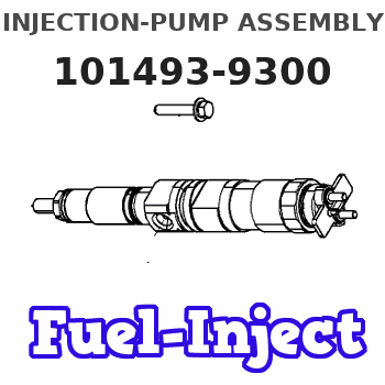
Information injection-pump assembly
ZEXEL
101493-9300
1014939300
Rating:
Service parts 101493-9300 INJECTION-PUMP ASSEMBLY:
1.
_
6.
COUPLING PLATE
7.
COUPLING PLATE
8.
_
9.
_
11.
Nozzle and Holder
12.
Open Pre:MPa(Kqf/cm2)
21.6{220}
15.
NOZZLE SET
Cross reference number
ZEXEL
101493-9300
1014939300
Zexel num
Bosch num
Firm num
Name
101493-9300
DPICO
INJECTION-PUMP ASSEMBLY
DB33 * Q
DB33 * Q
Calibration Data:
Adjustment conditions
Test oil
1404 Test oil ISO4113 or {SAEJ967d}
1404 Test oil ISO4113 or {SAEJ967d}
Test oil temperature
degC
40
40
45
Nozzle and nozzle holder
105780-8140
Bosch type code
EF8511/9A
Nozzle
105780-0000
Bosch type code
DN12SD12T
Nozzle holder
105780-2080
Bosch type code
EF8511/9
Opening pressure
MPa
17.2
Opening pressure
kgf/cm2
175
Injection pipe
Outer diameter - inner diameter - length (mm) mm 6-2-600
Outer diameter - inner diameter - length (mm) mm 6-2-600
Tester oil delivery pressure
kPa
157
157
157
Tester oil delivery pressure
kgf/cm2
1.6
1.6
1.6
Direction of rotation (viewed from drive side)
Right R
Right R
Injection timing adjustment
Direction of rotation (viewed from drive side)
Right R
Right R
Injection order
1-3-4-2
Pre-stroke
mm
3.4
3.35
3.45
Rack position
Point A R=A
Point A R=A
Beginning of injection position
Drive side NO.1
Drive side NO.1
Difference between angles 1
Cal 1-3 deg. 90 89.5 90.5
Cal 1-3 deg. 90 89.5 90.5
Difference between angles 2
Cal 1-4 deg. 180 179.5 180.5
Cal 1-4 deg. 180 179.5 180.5
Difference between angles 3
Cyl.1-2 deg. 270 269.5 270.5
Cyl.1-2 deg. 270 269.5 270.5
Injection quantity adjustment
Adjusting point
-
Rack position
10.3
Pump speed
r/min
1100
1100
1100
Average injection quantity
mm3/st.
56.7
55.1
58.3
Max. variation between cylinders
%
0
-2.5
2.5
Basic
*
Fixing the rack
*
Standard for adjustment of the maximum variation between cylinders
*
Injection quantity adjustment_02
Adjusting point
H
Rack position
9.5+-0.5
Pump speed
r/min
300
300
300
Average injection quantity
mm3/st.
8.6
7.1
10.1
Max. variation between cylinders
%
0
-14
14
Fixing the rack
*
Standard for adjustment of the maximum variation between cylinders
*
Injection quantity adjustment_03
Adjusting point
A
Rack position
R1(10.3)
Pump speed
r/min
1100
1100
1100
Average injection quantity
mm3/st.
56.7
55.7
57.7
Basic
*
Fixing the lever
*
Injection quantity adjustment_04
Adjusting point
B
Rack position
R1(10.3)
Pump speed
r/min
1800
1800
1800
Average injection quantity
mm3/st.
59.6
55.6
63.6
Fixing the lever
*
Injection quantity adjustment_05
Adjusting point
C
Rack position
R1-0.1
Pump speed
r/min
700
700
700
Average injection quantity
mm3/st.
41.9
38.7
45.1
Fixing the lever
*
Injection quantity adjustment_06
Adjusting point
I
Rack position
-
Pump speed
r/min
100
100
100
Average injection quantity
mm3/st.
56
48
64
Fixing the lever
*
Timer adjustment
Pump speed
r/min
1300--
Advance angle
deg.
0
0
0
Remarks
Start
Start
Timer adjustment_02
Pump speed
r/min
1250
Advance angle
deg.
0.6
Timer adjustment_03
Pump speed
r/min
1900
Advance angle
deg.
5
4.5
5.5
Remarks
Finish
Finish
Test data Ex:
Governor adjustment
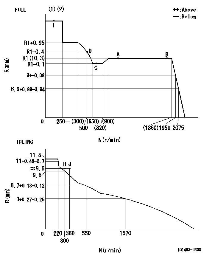
N:Pump speed
R:Rack position (mm)
(1)Torque cam stamping: T1
(2)Tolerance for racks not indicated: +-0.05mm.
----------
T1=D96
----------
----------
T1=D96
----------
Speed control lever angle

F:Full speed
I:Idle
(1)Stopper bolt set position 'H'
----------
----------
a=5.5deg+-5deg b=36deg+-3deg
----------
----------
a=5.5deg+-5deg b=36deg+-3deg
Stop lever angle
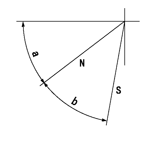
N:Pump normal
S:Stop the pump.
----------
----------
a=45deg+-5deg b=40deg+-5deg
----------
----------
a=45deg+-5deg b=40deg+-5deg
Timing setting

(1)Pump vertical direction
(2)Position of gear mark 'CC' at No 1 cylinder's beginning of injection
(3)B.T.D.C.: aa
(4)-
----------
aa=15deg
----------
a=(90deg)
----------
aa=15deg
----------
a=(90deg)
Information:
Illustration 21 shows the direction the rack moves when the fuel injector is receiving fuel.
Illustration 22 g01455811
Illustration 1 - Flowchart for the Air in Fuel Test (Test F)
Illustration 23 g01455812
Illustration 2 - Flowchart for the Air in Fuel Test (Test F)Fuel Injector Cranking Test (Test G)
Note: The fuel injector cranking test checks for worn out injectors by measuring the cranking rack.
Illustration 24 g01412134
(3) The rack control (4) The number one fuel injectorNote: Refer to Illustration 24 for the location of the rack control and the location of the number one injector.
Illustration 25 g01412115
Flowchart for the Fuel Injector Cranking Test (Test G)Fuel Shutoff Solenoid Test (Test H)
Note: The fuel shutoff solenoid test determines if the fuel shutoff solenoid and wiring harness are operating properly.
Illustration 26 g01412143
Flowchart for the Fuel Shutoff Solenoid Test (Test H)Fuel Ratio Control (FRC) Setting Test (Test I)
Note: The FRC setting test checks the FRC setting.
Illustration 27 g01412145
Flowchart for the Fuel Ratio Control (FRC) Setting Test (Test I)Governor Servo Retaining Ring Test (Test J)
Note: Do not run the engine during this test.Note: The governor servo retaining ring test checks for faulty internal parts of the governor.
Illustration 28 g01422811
(1) Paddle
Illustration 29 g01422821
(2) Clevis pin
Illustration 30 g01412147
Flowchart for the Governor Servo Retaining Ring Test (Test J)Fuel Transfer Pump Test (Test K)
Note: The fuel transfer pump test is a visual inspection of the fuel transfer pump components.
Illustration 31 g01412150
(1) Screen (2) Inlet check valve (3) Spring (4) Bolt (5) Piston (6) Outlet check valve (7) Freeze plug (8) Piston check valve (9) Passage (10) Tappet Assembly (11) CamNote: Refer to Illustration 31 for the location of the components for the fuel transfer pump.
Illustration 32 g01412149
Flowchart for the Fuel Transfer Pump Test (Test K)Fuel Ratio Control (FRC) Diaphragm Leak Test (Test L)
Note: The FRC diaphragm leak test checks for a leaking FRC diaphragm.
Illustration 33 g01412154
Flowchart for the Fuel Ratio Control (FRC) Diaphragm Leak Test (Test L)
Have questions with 101493-9300?
Group cross 101493-9300 ZEXEL
Dpico
101493-9300
INJECTION-PUMP ASSEMBLY
DB33
DB33