Information injection-pump assembly
BOSCH
F 01G 09U 02R
f01g09u02r
ZEXEL
101493-9170
1014939170
NISSAN
167000T023
167000t023
Rating:
Include in #1:
101452-3150
as _
Cross reference number
BOSCH
F 01G 09U 02R
f01g09u02r
ZEXEL
101493-9170
1014939170
NISSAN
167000T023
167000t023
Zexel num
Bosch num
Firm num
Name
Calibration Data:
Adjustment conditions
Test oil
1404 Test oil ISO4113 or {SAEJ967d}
1404 Test oil ISO4113 or {SAEJ967d}
Test oil temperature
degC
40
40
45
Nozzle and nozzle holder
105780-8140
Bosch type code
EF8511/9A
Nozzle
105780-0000
Bosch type code
DN12SD12T
Nozzle holder
105780-2080
Bosch type code
EF8511/9
Opening pressure
MPa
17.2
Opening pressure
kgf/cm2
175
Injection pipe
Outer diameter - inner diameter - length (mm) mm 6-2-600
Outer diameter - inner diameter - length (mm) mm 6-2-600
Overflow valve
131424-1520
Overflow valve opening pressure
kPa
157
123
191
Overflow valve opening pressure
kgf/cm2
1.6
1.25
1.95
Tester oil delivery pressure
kPa
157
157
157
Tester oil delivery pressure
kgf/cm2
1.6
1.6
1.6
Direction of rotation (viewed from drive side)
Right R
Right R
Injection timing adjustment
Direction of rotation (viewed from drive side)
Right R
Right R
Injection order
1-3-4-2
Pre-stroke
mm
3.2
3.15
3.25
Rack position
Point A R=A
Point A R=A
Beginning of injection position
Drive side NO.1
Drive side NO.1
Difference between angles 1
Cal 1-3 deg. 90 89.5 90.5
Cal 1-3 deg. 90 89.5 90.5
Difference between angles 2
Cal 1-4 deg. 180 179.5 180.5
Cal 1-4 deg. 180 179.5 180.5
Difference between angles 3
Cyl.1-2 deg. 270 269.5 270.5
Cyl.1-2 deg. 270 269.5 270.5
Injection quantity adjustment
Adjusting point
-
Rack position
12.1
Pump speed
r/min
1000
1000
1000
Average injection quantity
mm3/st.
66.5
64.9
68.1
Max. variation between cylinders
%
0
-2.5
2.5
Basic
*
Fixing the rack
*
Standard for adjustment of the maximum variation between cylinders
*
Injection quantity adjustment_02
Adjusting point
H
Rack position
9.5+-0.5
Pump speed
r/min
300
300
300
Average injection quantity
mm3/st.
9.6
7.8
11.4
Max. variation between cylinders
%
0
-15
15
Fixing the rack
*
Standard for adjustment of the maximum variation between cylinders
*
Injection quantity adjustment_03
Adjusting point
A
Rack position
R1(12.1)
Pump speed
r/min
1000
1000
1000
Average injection quantity
mm3/st.
66.5
65.5
67.5
Basic
*
Fixing the lever
*
Injection quantity adjustment_04
Adjusting point
B
Rack position
R1-0.1
Pump speed
r/min
1600
1600
1600
Average injection quantity
mm3/st.
72
68
76
Fixing the lever
*
Injection quantity adjustment_05
Adjusting point
I
Rack position
-
Pump speed
r/min
100
100
100
Average injection quantity
mm3/st.
100
84
116
Fixing the lever
*
Timer adjustment
Pump speed
r/min
(740)
Advance angle
deg.
0
0
0
Remarks
Measure speed (beginning of operation).
Measure speed (beginning of operation).
Timer adjustment_02
Pump speed
r/min
1050
Advance angle
deg.
1.3
0.8
1.8
Timer adjustment_03
Pump speed
r/min
1600
Advance angle
deg.
6
5.5
6.5
Remarks
Finish
Finish
Test data Ex:
Governor adjustment
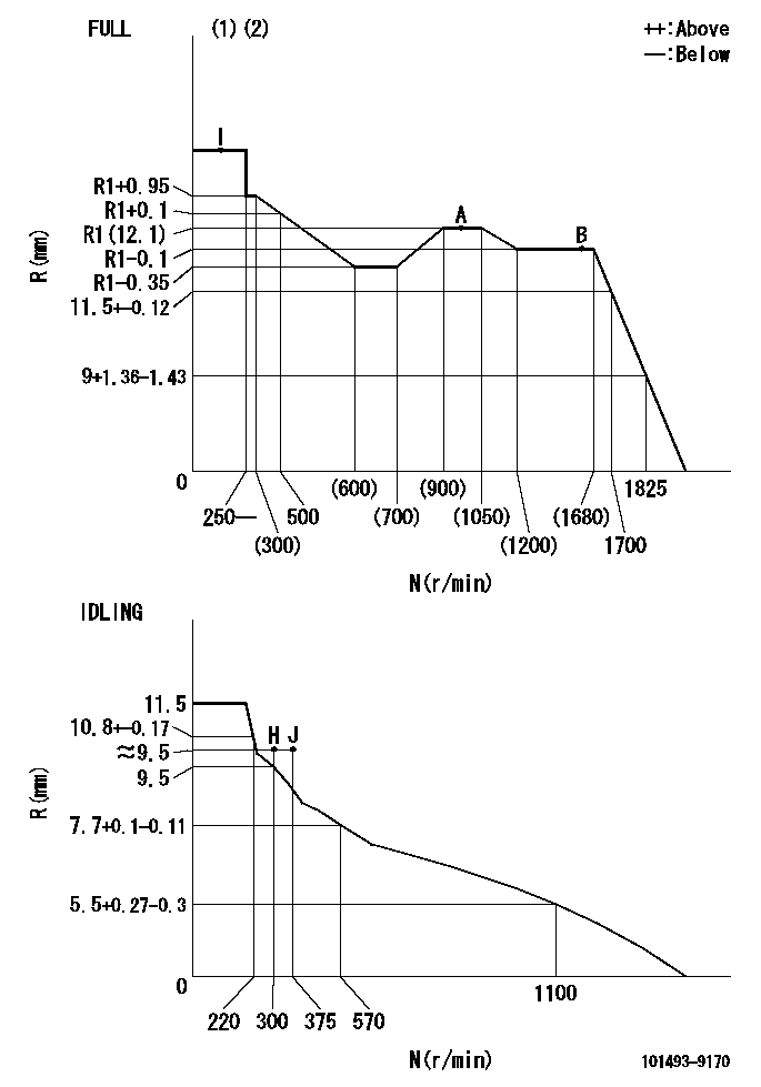
N:Pump speed
R:Rack position (mm)
(1)Torque cam stamping: T1
(2)Tolerance for racks not indicated: +-0.05mm.
----------
T1=G84
----------
----------
T1=G84
----------
Speed control lever angle
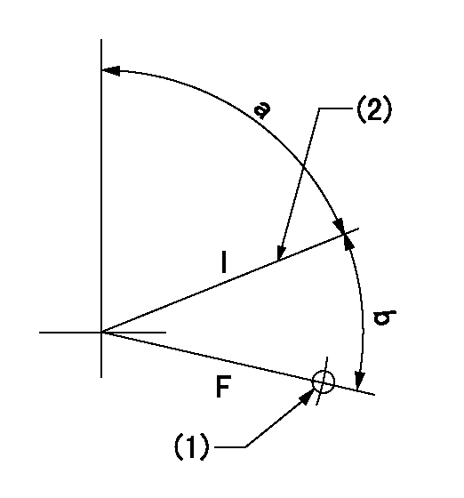
F:Full speed
I:Idle
(1)Use the hole at R = aa
(2)Stopper bolt set position 'H'
----------
aa=32mm
----------
a=70deg+-5deg b=37deg+-3deg
----------
aa=32mm
----------
a=70deg+-5deg b=37deg+-3deg
Stop lever angle

N:Pump normal
S:Stop the pump.
(1)Use the pin at R = aa
----------
aa=12mm
----------
a=29deg+-5deg b=10deg+-5deg
----------
aa=12mm
----------
a=29deg+-5deg b=10deg+-5deg
0000001501 ACS

(A) Set screw
(B) Push rod 1
(C) Push rod 2
(D) Cover
1. Aneroid compensator unit adjustment
(1)Select the push rod 2 to obtain L2.
(2)Screw in (A) to obtain L1.
2. Adjustment when mounting the governor.
(1)Set the speed of the pump to N1 r/min and fix the control lever at the full set position.
(2)Screw in the aneroid compensator to obtain the performance shown in the graph above.
(3)As there is hysterisis, measure when the absolute pressure drops.
(4)Hysterisis must not exceed rack position = h1.
----------
N1=1000r/min L1=(1.5)mm L2=11+-0.5mm h1=-
----------
Ra=R1(12.1)mm Rb=(R1-1.1)mm Pa=(89.3)+-2.7kPa((670)+-20mmHg) Pb=70.1+-0.7kPa(526+-5mmHg) Q1=66.5+-1cm3/1000st Q2=46.5+-1.6cm3/1000st
----------
N1=1000r/min L1=(1.5)mm L2=11+-0.5mm h1=-
----------
Ra=R1(12.1)mm Rb=(R1-1.1)mm Pa=(89.3)+-2.7kPa((670)+-20mmHg) Pb=70.1+-0.7kPa(526+-5mmHg) Q1=66.5+-1cm3/1000st Q2=46.5+-1.6cm3/1000st
Timing setting

(1)Pump vertical direction
(2)Position of gear's standard threaded hole (position of gear mark 'S') at No 1 cylinder's beginning of injection
(3)B.T.D.C.: aa
(4)-
----------
aa=11deg
----------
a=(60deg)
----------
aa=11deg
----------
a=(60deg)
Information:
Never use water alone as a coolant. Water alone is corrosive at engine operating temperatures. In addition, water alone does not provide adequate protection against boiling or freezing.
In engine cooling systems that use water alone, Caterpillar recommends the use of Cat SCA. Cat SCA helps to prevent the following conditions from occurring:
Corrosion
Formation of mineral deposits
Cavitation erosion of the cylinder liner
Foaming of the coolantIf Cat SCA is not used, select a fully formulated commercial SCA. The commercial SCA must provide a minimum of 2400 mg/L or 2400 ppm (140 grains/US gal) of nitrites in the final coolant mixture.The quality of the water is an important factor in this type of cooling system. Distilled water or deionized water is recommended for use in cooling systems. If distilled water or deionized water is not available, use water that meets or exceeds the minimum requirements that are listed in the table for recommended water properties in this Special Publication, "General Coolant Information" topic.A cooling system that uses a mixture of SCA and water only needs more SCA. The SCA concentration in a cooling system that uses SCA and water should be 6 to 8 percent by volume.Maintain the Cat SCA in the same way as you would maintain a cooling system that uses heavy-duty coolant/antifreeze. Adjust the maintenance for the amount ofCat SCA additions.Adding the Cat SCA to Water at the Initial Fill
Use the equation that is in this Special Publication, "Conventional Coolant/Antifreeze Cooling System Maintenance" to determine the amount of Cat SCA that is required at the initial fill. This equation is for a mixture of only Cat SCA and water.Adding the Cat SCA to Water for Maintenance
For the recommended service interval, refer to the Operation and Maintenance Manual, "Maintenance Interval Schedule" for your engine.Submit a coolant sample to your Cat dealer. See this Special Publication, "S O S Services Coolant Analysis" topic.Additions of Cat SCA are based on the results of the coolant analysis. The size of the cooling system determines the amount of Cat SCA that is required.Use the equation that is in this Special Publication, "Conventional Coolant/Antifreeze Cooling System Maintenance" to determine the amount of Cat SCA that is required for maintenance, if necessary:Note: Specific engine applications may require maintenance practices to be periodically evaluated in order to maintain properly the engine cooling system.SCA and part numbers are available from your Cat dealer.