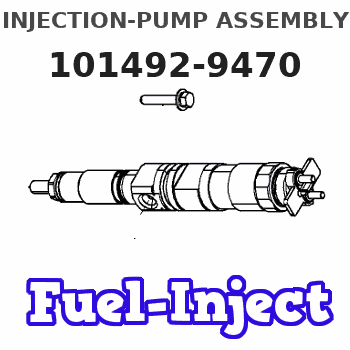
Information injection-pump assembly
BOSCH
F 019 Z10 967
f019z10967
ZEXEL
101492-9470
1014929470
Rating:
Service parts 101492-9470 INJECTION-PUMP ASSEMBLY:
1.
_
5.
AUTOM. ADVANCE MECHANIS
6.
COUPLING PLATE
8.
_
9.
_
11.
Nozzle and Holder
16600NA001
12.
Open Pre:MPa(Kqf/cm2)
18.1{185}
15.
NOZZLE SET
Cross reference number
BOSCH
F 019 Z10 967
f019z10967
ZEXEL
101492-9470
1014929470
Zexel num
Bosch num
Firm num
Name
101492-9470
F 019 Z10 967
INJECTION-PUMP ASSEMBLY
BD30T 14BC INJECTION PUMP ASSY PE4A,5A, PE
BD30T 14BC INJECTION PUMP ASSY PE4A,5A, PE
F 019 Z10 967
16790NA005 NISSAN-DIESEL
INJECTION-PUMP ASSEMBLY
BD30T * K 14BC INJECTION PUMP ASSY PE4A,5A, PE
BD30T * K 14BC INJECTION PUMP ASSY PE4A,5A, PE
Calibration Data:
Adjustment conditions
Test oil
1404 Test oil ISO4113 or {SAEJ967d}
1404 Test oil ISO4113 or {SAEJ967d}
Test oil temperature
degC
40
40
45
Nozzle and nozzle holder
105780-8140
Bosch type code
EF8511/9A
Nozzle
105780-0000
Bosch type code
DN12SD12T
Nozzle holder
105780-2080
Bosch type code
EF8511/9
Opening pressure
MPa
17.2
Opening pressure
kgf/cm2
175
Injection pipe
Outer diameter - inner diameter - length (mm) mm 6-2-600
Outer diameter - inner diameter - length (mm) mm 6-2-600
Overflow valve
131424-1520
Overflow valve opening pressure
kPa
157
123
191
Overflow valve opening pressure
kgf/cm2
1.6
1.25
1.95
Tester oil delivery pressure
kPa
157
157
157
Tester oil delivery pressure
kgf/cm2
1.6
1.6
1.6
Direction of rotation (viewed from drive side)
Right R
Right R
Injection timing adjustment
Direction of rotation (viewed from drive side)
Right R
Right R
Injection order
1-3-4-2
Pre-stroke
mm
3.4
3.35
3.45
Beginning of injection position
Drive side NO.1
Drive side NO.1
Difference between angles 1
Cal 1-3 deg. 90 89.5 90.5
Cal 1-3 deg. 90 89.5 90.5
Difference between angles 2
Cal 1-4 deg. 180 179.5 180.5
Cal 1-4 deg. 180 179.5 180.5
Difference between angles 3
Cyl.1-2 deg. 270 269.5 270.5
Cyl.1-2 deg. 270 269.5 270.5
Injection quantity adjustment
Adjusting point
A
Rack position
10.8
Pump speed
r/min
1300
1300
1300
Average injection quantity
mm3/st.
74.5
73.5
75.5
Max. variation between cylinders
%
0
-3.5
3.5
Basic
*
Fixing the lever
*
Boost pressure
kPa
88
88
Boost pressure
mmHg
660
660
Injection quantity adjustment_02
Adjusting point
C
Rack position
8.5+-0.5
Pump speed
r/min
350
350
350
Average injection quantity
mm3/st.
12
10
14
Max. variation between cylinders
%
0
-10
10
Fixing the rack
*
Boost pressure
kPa
0
0
0
Boost pressure
mmHg
0
0
0
Injection quantity adjustment_03
Adjusting point
E
Rack position
11++
Pump speed
r/min
100
100
100
Average injection quantity
mm3/st.
70
70
80
Fixing the lever
*
Boost pressure
kPa
0
0
0
Boost pressure
mmHg
0
0
0
Rack limit
*
Boost compensator adjustment
Pump speed
r/min
900
900
900
Rack position
R1-1.05
Boost pressure
kPa
14.7
9.4
20
Boost pressure
mmHg
110
70
150
Boost compensator adjustment_02
Pump speed
r/min
900
900
900
Rack position
R1(10.8)
Boost pressure
kPa
74.6
71.9
77.3
Boost pressure
mmHg
560
540
580
Test data Ex:
Governor adjustment
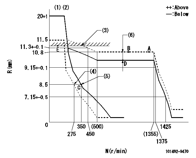
N:Pump speed
R:Rack position (mm)
(1)Target notch: K
(2)Tolerance for racks not indicated: +-0.05mm.
(3)RACK LIMIT
(4)Set idle sub-spring
(5)Main spring setting
(6)Boost compensator stroke: BCL
----------
K=15 BCL=1.05+-0.1mm
----------
----------
K=15 BCL=1.05+-0.1mm
----------
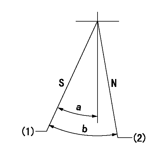
Speed control lever angle

F:Full speed
I:Idle
(1)Stopper bolt setting
----------
----------
a=30deg+-5deg b=25deg+-5deg
----------
----------
a=30deg+-5deg b=25deg+-5deg
Stop lever angle
N:Pump normal
S:Stop the pump.
(1)Rack position = aa, speed = bb (stamp at delivery)
(2)Normal
----------
aa=1-0.5mm bb=0r/min
----------
a=44.5deg+-5deg b=(55deg)
----------
aa=1-0.5mm bb=0r/min
----------
a=44.5deg+-5deg b=(55deg)
Timing setting

(1)Pump vertical direction
(2)Position of gear mark 'ZZ' at No 1 cylinder's beginning of injection
(3)-
(4)-
----------
----------
a=(100deg)
----------
----------
a=(100deg)
Information:
Use the following tests for troubleshooting and repair steps. Use the ""Test for Cylinder Cutout"" in order to determine if the replacement of individual injectors is needed. Replace suspect injectors with the part number of the original injector. Use the ""Test for Leakage from Poppet Valve"" in order to determine if the full set of injectors need to be replaced. For replacement of the full set of injectors, use the current injectors and new software that is listed in Table 2.Test for Cylinder Cutout
The cylinder cutout test should be used in order to determine if an individual injector may have caused the failure.
Warm the engine out of cold mode.
Connect Cat ET to the engine while the engine is running.
Ensure that the engine speed is 1200 rpm 125 rpm. An extremely rough running engine will need to be diagnosed by other methods.
Cut out one bank of cylinders. Note engine rpm and the fuel position on the Cat ET screen at that time.
Cut out one of the remaining cylinders from the cylinder bank that is running. Allow the engine to stabilize, and note the fuel position.
Give power back to that cylinder. Allow the engine to stabilize. Note the fuel position.
Repeat steps 5 through 6 until the cylinder bank has been completely checked.
Power all cylinders. Allow the engine to stabilize.
Cut out the other cylinder bank and repeat steps 5 through 8.
Repeat steps 4 through 9 with the engine at 2000 rpm.
Compare the results from the fuel position from each cylinder.
If the cylinder was cut out and the fuel position did not change the cylinder may not have been producing power. This cylinder would be suspect.
When you are finished with the test, reduce engine RPM to low idle. Shut off the engine.
Replace any suspect injector with a similar original injector. Install new seals for the injector and the jumper tube during this repair. The repair procedure for the injector is found in Special Instruction, REHS0116.It is possible that multiple injectors are functioning improperly. Complete ""Test for Leakage from Poppet Valve"" in order to evaluate possible excessive leakage from the injectors.Test for Leakage from Poppet Valve
Warm the engine out of Cold Mode to normal operating temperature.
Turn off the engine.
Remove the valve cover bolts in preparation in order to observe the injectors. Leave the covers in place.
Hot oil and components can cause personal injury.Do not allow hot oil or components to contact skin.
Restart the engine and run at low idle with no load.
Use Cat ET in order to perform the test that overrides the injection actuation system. Increase injection actuation pressure to the maximum value.
Observe all of the injectors under each valve cover for leakage at the spill port. A small amount of dripping is acceptable. However, a continuous stream of oil is an indication of excessive leakage of the poppet valve. Only leaks at the spill port are an indication of excessive leakage from the poppet valve.
If multiple injectors display excessive leakage from the poppet valves, update the set of injectors with
Have questions with 101492-9470?
Group cross 101492-9470 ZEXEL
Hyundai
Dpico
Hyundai
Dpico
Nissan-Diesel
Nissan-Diesel
101492-9470
F 019 Z10 967
INJECTION-PUMP ASSEMBLY
BD30T
BD30T