Information injection-pump assembly
ZEXEL
101492-9460
1014929460
NISSAN-DIESEL
16712NA005
16712na005
Rating:
Cross reference number
ZEXEL
101492-9460
1014929460
NISSAN-DIESEL
16712NA005
16712na005
Zexel num
Bosch num
Firm num
Name
Calibration Data:
Adjustment conditions
Test oil
1404 Test oil ISO4113 or {SAEJ967d}
1404 Test oil ISO4113 or {SAEJ967d}
Test oil temperature
degC
40
40
45
Nozzle and nozzle holder
105780-8140
Bosch type code
EF8511/9A
Nozzle
105780-0000
Bosch type code
DN12SD12T
Nozzle holder
105780-2080
Bosch type code
EF8511/9
Opening pressure
MPa
17.2
Opening pressure
kgf/cm2
175
Injection pipe
Outer diameter - inner diameter - length (mm) mm 6-2-600
Outer diameter - inner diameter - length (mm) mm 6-2-600
Overflow valve
131424-1520
Overflow valve opening pressure
kPa
157
123
191
Overflow valve opening pressure
kgf/cm2
1.6
1.25
1.95
Tester oil delivery pressure
kPa
157
157
157
Tester oil delivery pressure
kgf/cm2
1.6
1.6
1.6
Direction of rotation (viewed from drive side)
Right R
Right R
Injection timing adjustment
Direction of rotation (viewed from drive side)
Right R
Right R
Injection order
1-3-4-2
Pre-stroke
mm
3.4
3.35
3.45
Beginning of injection position
Drive side NO.1
Drive side NO.1
Difference between angles 1
Cal 1-3 deg. 90 89.5 90.5
Cal 1-3 deg. 90 89.5 90.5
Difference between angles 2
Cal 1-4 deg. 180 179.5 180.5
Cal 1-4 deg. 180 179.5 180.5
Difference between angles 3
Cyl.1-2 deg. 270 269.5 270.5
Cyl.1-2 deg. 270 269.5 270.5
Injection quantity adjustment
Adjusting point
A
Rack position
11
Pump speed
r/min
750
750
750
Average injection quantity
mm3/st.
71.5
70.5
72.5
Max. variation between cylinders
%
0
-3.5
3.5
Basic
*
Fixing the lever
*
Injection quantity adjustment_02
Adjusting point
-
Rack position
8.3+-0.5
Pump speed
r/min
500
500
500
Average injection quantity
mm3/st.
8
6
10
Max. variation between cylinders
%
0
-10
10
Fixing the rack
*
Remarks
Adjust only variation between cylinders; adjust governor according to governor specifications.
Adjust only variation between cylinders; adjust governor according to governor specifications.
Injection quantity adjustment_03
Adjusting point
C
Rack position
11.2++
Pump speed
r/min
100
100
100
Average injection quantity
mm3/st.
70
70
80
Fixing the lever
*
Rack limit
*
Test data Ex:
Governor adjustment
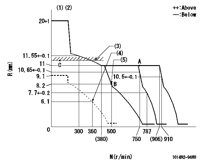
N:Pump speed
R:Rack position (mm)
(1)Target notch: K
(2)Tolerance for racks not indicated: +-0.05mm.
(3)RACK LIMIT
(4)Set idle sub-spring
(5)Main spring setting
----------
K=12
----------
----------
K=12
----------
Speed control lever angle
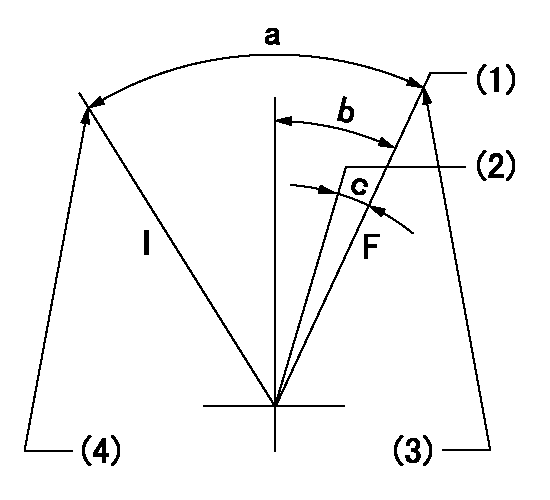
F:Full speed
I:Idle
(1)Set the pump speed at aa. ( At delivery )
(2)When pump speed set at bb
(3)Stopper bolt setting
(4)Stopper bolt setting
----------
aa=910r/min bb=750r/min
----------
a=18deg+-5deg b=11deg+-5deg c=7deg+-5deg
----------
aa=910r/min bb=750r/min
----------
a=18deg+-5deg b=11deg+-5deg c=7deg+-5deg
Stop lever angle

N:Pump normal
S:Stop the pump.
(1)Normal
----------
----------
a=12deg+-5deg b=50deg+-5deg
----------
----------
a=12deg+-5deg b=50deg+-5deg
0000001501 GOV FULL LOAD ADJUSTMENT
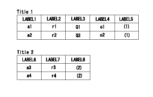
Title1:Full load stopper adjustment
Title2:Governor set speed
LABEL1:Distinguishing
LABEL2:Pump speed (r/min)
LABEL3:Ave. injection quantity (mm3/st)
LABEL4:Max. var. bet. cyl.
LABEL5:Remarks
LABEL6:Distinguishing
LABEL7:Governor set speed (r/min)
LABEL8:Remarks
(1)Adjustment conditions are the same as those for measuring injection quantity.
(2)-
----------
----------
a1=B a2=- r1=750r/min r2=- Q1=71.5+-1mm3/st Q2=- c1=+-3.5% c2=- a3=18 a4=15 r3=900r/min r4=750r/min
----------
----------
a1=B a2=- r1=750r/min r2=- Q1=71.5+-1mm3/st Q2=- c1=+-3.5% c2=- a3=18 a4=15 r3=900r/min r4=750r/min
Timing setting

(1)Pump vertical direction
(2)Position of gear mark 'ZZ' at No 1 cylinder's beginning of injection
(3)B.T.D.C.: aa
(4)-
----------
aa=8deg
----------
a=(100deg)
----------
aa=8deg
----------
a=(100deg)
Information:
LOADERS
992G (7HR1-Up)Reference: Tool Operating Manual, form NEHS0537 4C6090 Temp. Selector GPProblem:
We have received reports, (also from 3400E HEUI Engines), about difficulties to pin-point "faulty" injectors with the help of ET. This is especially the case, if a cylinder is not completely "cold". Fortunately, we have a second, very effective tool/method, to quickly find "faulty" injectors for 3500 Series Engines. This tool does not replace ET, it complements ET (ET = Electronic Technician).Solution:
The solution is the 4C6090 Multi Channel Temperature Selector Gp, to measure & compare individual cylinder temperatures. This is a fairly inexpensive, but if used correctly, a highly effective tool (those of you, who have worked already on Marine Engines, may agree). Caution: Read also the chapter: "Cold Cylinder Cut-Out" in the Service Manual, before running this test. Test procedure: AAInstall the tool and the 4C6093 1-8 channel cable pack (for 12 & 16 cylinder Engines you need to order a second 8 channel cable pack) on the "cold" Engine. Check all 7E6830 thermocouples. Replace as necessary. Write down all "cold" individual cylinder and the ambient temperature(s). Caution: Each multi channel temperature test is: Engine, site, test individual! BBStart the Engine & let it warm up at LI: do not read any individual cylinder temperatures until you are 100% sure that all Engine temperatures have stabilized ! (LI = Low Idle) Write down the LI individual cylinder temperatures on the same chart as above. CCSelect Engine HI. - Read all individual cylinder temperatures, once the temperatures have stabilized ! Caution: On Engines with thermostatically controlled SCAC systems, your test may get fouled up by a sudden inrush of "cold" coolant, when the SCAC thermostats open ! (HI = High Idle, SCAC = Separate Circuit After Cooler) Write down the HI individual Engine cylinder temperatures on the same chart. DDThe Tool Operating Manual also discusses to do this test in Torque Converter Stall Conditions. If you manage to do this without "grilling" the TC and/or the Oil, by all means, give it a try. The importance is to get good, valid data, that allows you to make a decision about yes or no for possible injector replacement. Go, no-go tolerance band for possibly "good/faulty" injectors.For each test (Cold, LI, HI, & maybe TC-Stall) take all individual cylinder temperatures and add them up. Then, divide this figure by the number of cylinders (for the 992G, that would be 8). This is your average 0-Line, or, averaged cylinder temperatures. Example: Say, at High Idle you find for no. 1 to 8 cylinders: 736F, 701F, 756F, 695F, 728F, 714F, 682F, 732F. - Hence, your 0-line would be: 718 Deg F. This 0-Line has to be re-established for each test, each Engine, each Site, every time you run/re-run this test ! From the 0-Line, the tolerance band is plus/minus 42 degrees C (75 Deg F). I.e. any cylinder that falls outside the tolerance band of a total of 84 degrees C. (150 Deg F), needs further investigation, and possibly an