Information injection-pump assembly
ZEXEL
101492-9450
1014929450
NISSAN-DIESEL
16712NA004
16712na004
Rating:
Cross reference number
ZEXEL
101492-9450
1014929450
NISSAN-DIESEL
16712NA004
16712na004
Zexel num
Bosch num
Firm num
Name
Calibration Data:
Adjustment conditions
Test oil
1404 Test oil ISO4113 or {SAEJ967d}
1404 Test oil ISO4113 or {SAEJ967d}
Test oil temperature
degC
40
40
45
Nozzle and nozzle holder
105780-8140
Bosch type code
EF8511/9A
Nozzle
105780-0000
Bosch type code
DN12SD12T
Nozzle holder
105780-2080
Bosch type code
EF8511/9
Opening pressure
MPa
17.2
Opening pressure
kgf/cm2
175
Injection pipe
Outer diameter - inner diameter - length (mm) mm 6-2-600
Outer diameter - inner diameter - length (mm) mm 6-2-600
Overflow valve
131424-1520
Overflow valve opening pressure
kPa
157
123
191
Overflow valve opening pressure
kgf/cm2
1.6
1.25
1.95
Tester oil delivery pressure
kPa
157
157
157
Tester oil delivery pressure
kgf/cm2
1.6
1.6
1.6
Direction of rotation (viewed from drive side)
Right R
Right R
Injection timing adjustment
Direction of rotation (viewed from drive side)
Right R
Right R
Injection order
1-3-4-2
Pre-stroke
mm
3.4
3.35
3.45
Beginning of injection position
Drive side NO.1
Drive side NO.1
Difference between angles 1
Cal 1-3 deg. 90 89.5 90.5
Cal 1-3 deg. 90 89.5 90.5
Difference between angles 2
Cal 1-4 deg. 180 179.5 180.5
Cal 1-4 deg. 180 179.5 180.5
Difference between angles 3
Cyl.1-2 deg. 270 269.5 270.5
Cyl.1-2 deg. 270 269.5 270.5
Injection quantity adjustment
Adjusting point
A
Rack position
11
Pump speed
r/min
750
750
750
Average injection quantity
mm3/st.
71.5
70.5
72.5
Max. variation between cylinders
%
0
-3.5
3.5
Basic
*
Fixing the lever
*
Injection quantity adjustment_02
Adjusting point
-
Rack position
8.3+-0.5
Pump speed
r/min
500
500
500
Average injection quantity
mm3/st.
8
6
10
Max. variation between cylinders
%
0
-10
10
Fixing the rack
*
Remarks
Adjust only variation between cylinders; adjust governor according to governor specifications.
Adjust only variation between cylinders; adjust governor according to governor specifications.
Injection quantity adjustment_03
Adjusting point
C
Rack position
11.2++
Pump speed
r/min
100
100
100
Average injection quantity
mm3/st.
70
70
80
Fixing the lever
*
Rack limit
*
Test data Ex:
Governor adjustment
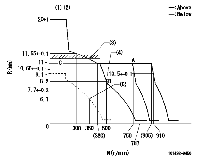
N:Pump speed
R:Rack position (mm)
(1)Target notch: K
(2)Tolerance for racks not indicated: +-0.05mm.
(3)RACK LIMIT
(4)Main spring setting
(5)Set idle sub-spring
----------
K=12
----------
----------
K=12
----------
Speed control lever angle
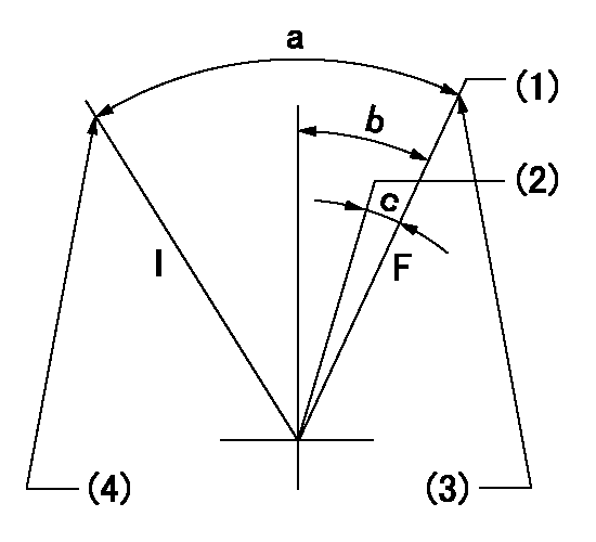
F:Full speed
I:Idle
(1)Set the pump speed at aa. ( At delivery )
(2)When pump speed set at bb
(3)Stopper bolt setting
(4)Stopper bolt setting
----------
aa=910r/min bb=750r/min
----------
a=18deg+-5deg b=11deg+-5deg c=7deg+-5deg
----------
aa=910r/min bb=750r/min
----------
a=18deg+-5deg b=11deg+-5deg c=7deg+-5deg
Stop lever angle
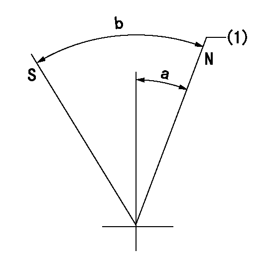
N:Pump normal
S:Stop the pump.
(1)Normal
----------
----------
a=12deg+-5deg b=50deg+-5deg
----------
----------
a=12deg+-5deg b=50deg+-5deg
0000001501 GOV FULL LOAD ADJUSTMENT
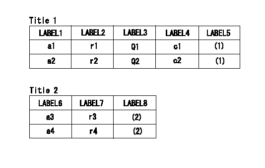
Title1:Full load stopper adjustment
Title2:Governor set speed
LABEL1:Distinguishing
LABEL2:Pump speed (r/min)
LABEL3:Ave. injection quantity (mm3/st)
LABEL4:Max. var. bet. cyl.
LABEL5:Remarks
LABEL6:Distinguishing
LABEL7:Governor set speed (r/min)
LABEL8:Remarks
(1)Adjustment conditions are the same as those for measuring injection quantity.
(2)-
----------
----------
a1=B a2=- r1=750r/min r2=- Q1=71.5+-1mm3/st Q2=- c1=+-3.5% c2=- a3=18 a4=15 r3=900r/min r4=750r/min
----------
----------
a1=B a2=- r1=750r/min r2=- Q1=71.5+-1mm3/st Q2=- c1=+-3.5% c2=- a3=18 a4=15 r3=900r/min r4=750r/min
Timing setting

(1)Pump vertical direction
(2)Position of gear mark 'ZZ' at No 1 cylinder's beginning of injection
(3)B.T.D.C.: aa
(4)-
----------
aa=8deg
----------
a=(100deg)
----------
aa=8deg
----------
a=(100deg)
Information:
PARTS NEEDED
Qty
Part Number Description
4 8T2223 BOLT-SOCKET HD
1 8T9524 SEAL-O-RING
1 20R5566 INJECTOR GP-FUEL
1 2287089 SEAL-O-RING-ORFS
1 2287100 SEAL-O-RING-STOR
1 2287108 SEAL-O-RING-STOR
1 2300940 SEAL-PIP
1 2697852 SEAL-O-RING
1 3170808 SEAL-O-RING
In order to allow equitable parts availability to all participating dealers, please limit your initial parts order to not exceed 1% of dealership population. This is an initial order recommendation only, and the ultimate responsibility for ordering the total number of parts needed to satisfy the program lies with the dealer.
ACTION REQUIRED
Perform a Fuel Status Verification Test (FSVT). Follow all procedures outlined in KENR5398.
Replace injectors showing INJ-2, INJ-7 or INJ-12 codes. Schedule the replacement in line with the 1500 hour recommendation described in KENR5398.
Refer to KENR6052 for removal and installation instructions.
To qualify for this program:
Machine must be operating the most current software release in SIS Web.
Machine must be operating with the Clean Fuel Module (CFM) installed and activated.
Attach a Product Status Report to the claim form.
Provide injector replacement tracking sheet copy for specific machine SN on claim.
Conduct a review of the maintenance history of the machine to ensure no High Pressure Fuel Pump failure occurred within 250 service hours of an injector failure. If a high pressure fuel pump has failed, inspect the 2D inline filter for damage and/or debris.
Must have fuel samples from month of failure with passing (green/no action suggested) fuel quality report. Program Administrator will audit if fuel sample program is being executed per agreement.
Failure to provide the requested information and/or the failed injector could result in a claim being debited or rejected.
SERVICE CLAIM ALLOWANCES
Product smu/age whichever comes first Caterpillar Dealer Suggested Customer Suggested
Parts % Labor Hrs% Parts % Labor Hrs% Parts % Labor Hrs%
0-6000 hrs,
0-12 mo 100.0% 100.0% 0.0% 0.0% 0.0% 0.0%
6001-12000 hrs,
13-24 mo 100.0% 50.0% 0.0% 0.0% 0.0% 50.0%
This is a 2.0-hour job
If there has been a previous repair, part age/hours will apply. Retain a copy of the previous repair invoice in the dealer's records for audit purposes, and specify repair date and machine hours in the "Additional Comments" section of the warranty claim.
PARTS DISPOSITION
Hold all fuel injectors for a Parts Return Request (PRR). A Parts Return Request (PRR) will be issued to you through the Send-It-Back process after the claim is submitted. Make sure to list the service letter program number on the packing slip and include the closed work order paperwork. Handle all other parts in accordance with your Warranty Bulletin on warranty parts handling.
If a Parts Return Request (PRR) is not issued to you after 30 days through the Send-It-Back process, handle the parts in accordance with your warranty bulletin on warranty parts handling.