Information injection-pump assembly
BOSCH
9 400 619 753
9400619753
ZEXEL
101492-9260
1014929260
NISSAN-DIESEL
1671290165
1671290165

Rating:
Service parts 101492-9260 INJECTION-PUMP ASSEMBLY:
1.
_
5.
AUTOM. ADVANCE MECHANIS
6.
COUPLING PLATE
8.
_
9.
_
11.
Nozzle and Holder
1660090068
12.
Open Pre:MPa(Kqf/cm2)
19.6{200}
15.
NOZZLE SET
Cross reference number
BOSCH
9 400 619 753
9400619753
ZEXEL
101492-9260
1014929260
NISSAN-DIESEL
1671290165
1671290165
Zexel num
Bosch num
Firm num
Name
101492-9260
9 400 619 753
1671290165 NISSAN-DIESEL
INJECTION-PUMP ASSEMBLY
FD35 * K
FD35 * K
Calibration Data:
Adjustment conditions
Test oil
1404 Test oil ISO4113 or {SAEJ967d}
1404 Test oil ISO4113 or {SAEJ967d}
Test oil temperature
degC
40
40
45
Nozzle and nozzle holder
105780-8140
Bosch type code
EF8511/9A
Nozzle
105780-0000
Bosch type code
DN12SD12T
Nozzle holder
105780-2080
Bosch type code
EF8511/9
Opening pressure
MPa
17.2
Opening pressure
kgf/cm2
175
Injection pipe
Outer diameter - inner diameter - length (mm) mm 6-2-600
Outer diameter - inner diameter - length (mm) mm 6-2-600
Tester oil delivery pressure
kPa
157
157
157
Tester oil delivery pressure
kgf/cm2
1.6
1.6
1.6
Direction of rotation (viewed from drive side)
Right R
Right R
Injection timing adjustment
Direction of rotation (viewed from drive side)
Right R
Right R
Injection order
1-3-4-2
Pre-stroke
mm
3.4
3.35
3.45
Beginning of injection position
Drive side NO.1
Drive side NO.1
Difference between angles 1
Cal 1-3 deg. 90 89.5 90.5
Cal 1-3 deg. 90 89.5 90.5
Difference between angles 2
Cal 1-4 deg. 180 179.5 180.5
Cal 1-4 deg. 180 179.5 180.5
Difference between angles 3
Cyl.1-2 deg. 270 269.5 270.5
Cyl.1-2 deg. 270 269.5 270.5
Injection quantity adjustment
Adjusting point
A
Rack position
11.5
Pump speed
r/min
750
750
750
Average injection quantity
mm3/st.
47.6
46.6
48.6
Max. variation between cylinders
%
0
-2.5
2.5
Basic
*
Fixing the lever
*
Injection quantity adjustment_02
Adjusting point
-
Rack position
9.3+-0.5
Pump speed
r/min
400
400
400
Average injection quantity
mm3/st.
9
7
11
Max. variation between cylinders
%
0
-15
15
Fixing the rack
*
Remarks
Adjust only variation between cylinders; adjust governor according to governor specifications.
Adjust only variation between cylinders; adjust governor according to governor specifications.
Test data Ex:
Governor adjustment
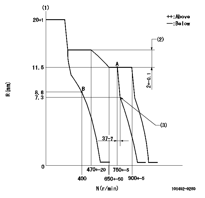
N:Pump speed
R:Rack position (mm)
(1)Target notch: K
(2)Rack difference between N = N1 and N = N2
(3)Idle sub spring setting: L1.
----------
K=13 N1=750r/min N2=400r/min L1=7.3-0.5mm
----------
----------
K=13 N1=750r/min N2=400r/min L1=7.3-0.5mm
----------
Speed control lever angle
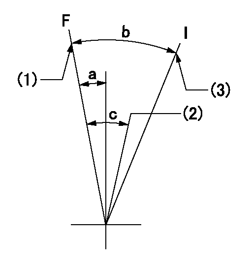
F:Full speed
I:Idle
(1)Set the pump speed at aa. ( At delivery )
(2)Set the pump speed at bb.
(3)Stopper bolt setting
----------
aa=900r/min bb=750r/min
----------
a=4deg+-5deg b=26deg+-5deg c=7deg+-5deg
----------
aa=900r/min bb=750r/min
----------
a=4deg+-5deg b=26deg+-5deg c=7deg+-5deg
Stop lever angle
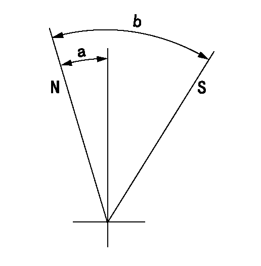
N:Pump normal
S:Stop the pump.
----------
----------
a=26.5deg+-5deg b=53deg+-5deg
----------
----------
a=26.5deg+-5deg b=53deg+-5deg
0000001501 GOV FULL LOAD ADJUSTMENT
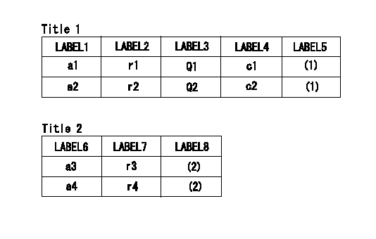
Title1:Full load stopper adjustment
Title2:Governor set speed
LABEL1:Distinguishing
LABEL2:Pump speed (r/min)
LABEL3:Ave. injection quantity (mm3/st)
LABEL4:Max. var. bet. cyl.
LABEL5:Remarks
LABEL6:Distinguishing
LABEL7:Governor set speed (r/min)
LABEL8:Remarks
(1)Adjustment conditions are the same as those for measuring injection quantity.
(2)-
----------
----------
a1=A a2=- r1=750r/min r2=- Q1=47.6+-1mm3/st Q2=- c1=+-2.5% c2=- a3=18 a4=15 r3=900r/min r4=750r/min
----------
----------
a1=A a2=- r1=750r/min r2=- Q1=47.6+-1mm3/st Q2=- c1=+-2.5% c2=- a3=18 a4=15 r3=900r/min r4=750r/min
Timing setting

(1)Pump vertical direction
(2)Position of gear's standard threaded hole (position of gear mark 'N') at No 1 cylinder's beginning of injection
(3)-
(4)-
----------
----------
a=(60deg)
----------
----------
a=(60deg)
Information:
14May2018
U-275
A-204
D-241
O-246
Parts stock action only
PRODUCT IMPROVEMENT PROGRAM FOR REMOVING 224-4536 CHANGE 06 INJECTION ACTUATION PRESSURE SENSORS FROM DEALER PARTS STOCK
7750 PI70708
Caterpillar’s obligations under this Service Letter are subject to, and shall not apply in contravention of, the laws, rules, regulations, directives, ordinances, orders, or statutes of the United States, or of any other applicable jurisdiction, without recourse or liability with respect to Caterpillar.
When submitting claim for Parts Stock Action, Use the appropriate 99Z as the s/n, the appropriate Service Letter Program Number as the Part number in the Part Causing Failure field, "7751" as the Group Number, "56" as the Description Code.
The information supplied in this service letter may not be valid after the termination date of this program.Do not perform the work outlined in this Service Letter after the termination date without first contacting your Caterpillar product analyst.
TERMINATION DATE
31Aug2018
PROBLEM
224-4536 change 06 Injector Actuation Pressure Sensor may fail if placed into service.
ACTION REQUIRED
Remove 224-4536 change 06 Injector Actuation Pressure Sensors from dealer parts stock. Image 1 shows a picture of the sensor to remove from the shelves.
Image1
Image2
SERVICE CLAIM ALLOWANCES
Submit one claim for all parts removed from dealer parts stock.
PARTS DISPOSITION
Handle the parts in accordance with your Warranty Bulletin on warranty parts handling.
Have questions with 101492-9260?
Group cross 101492-9260 ZEXEL
Nissan-Diesel
Mitsubishi-Heav
Nissan-Diesel
Daewoo
Nissan-Diesel
101492-9260
9 400 619 753
1671290165
INJECTION-PUMP ASSEMBLY
FD35
FD35