Information injection-pump assembly
ZEXEL
101492-9090
1014929090
NISSAN-DIESEL
1671290114
1671290114
Rating:
Service parts 101492-9090 INJECTION-PUMP ASSEMBLY:
1.
_
5.
AUTOM. ADVANCE MECHANIS
6.
COUPLING PLATE
8.
_
9.
_
11.
Nozzle and Holder
16600T9303
12.
Open Pre:MPa(Kqf/cm2)
19.6(200)
14.
NOZZLE
15.
NOZZLE SET
Cross reference number
ZEXEL
101492-9090
1014929090
NISSAN-DIESEL
1671290114
1671290114
Zexel num
Bosch num
Firm num
Name
Calibration Data:
Adjustment conditions
Test oil
1404 Test oil ISO4113 or {SAEJ967d}
1404 Test oil ISO4113 or {SAEJ967d}
Test oil temperature
degC
40
40
45
Nozzle and nozzle holder
105780-8140
Bosch type code
EF8511/9A
Nozzle
105780-0000
Bosch type code
DN12SD12T
Nozzle holder
105780-2080
Bosch type code
EF8511/9
Opening pressure
MPa
17.2
Opening pressure
kgf/cm2
175
Injection pipe
Outer diameter - inner diameter - length (mm) mm 6-2-600
Outer diameter - inner diameter - length (mm) mm 6-2-600
Overflow valve
131424-6120
Overflow valve opening pressure
kPa
191
157
225
Overflow valve opening pressure
kgf/cm2
1.95
1.6
2.3
Tester oil delivery pressure
kPa
157
157
157
Tester oil delivery pressure
kgf/cm2
1.6
1.6
1.6
Direction of rotation (viewed from drive side)
Right R
Right R
Injection timing adjustment
Direction of rotation (viewed from drive side)
Right R
Right R
Injection order
1-3-4-2
Pre-stroke
mm
3.4
3.35
3.45
Beginning of injection position
Drive side NO.1
Drive side NO.1
Difference between angles 1
Cal 1-3 deg. 90 89.5 90.5
Cal 1-3 deg. 90 89.5 90.5
Difference between angles 2
Cal 1-4 deg. 180 179.5 180.5
Cal 1-4 deg. 180 179.5 180.5
Difference between angles 3
Cyl.1-2 deg. 270 269.5 270.5
Cyl.1-2 deg. 270 269.5 270.5
Injection quantity adjustment
Adjusting point
A
Rack position
11.1
Pump speed
r/min
750
750
750
Average injection quantity
mm3/st.
44.7
43.7
45.7
Max. variation between cylinders
%
0
-3.5
3.5
Basic
*
Fixing the lever
*
Injection quantity adjustment_02
Adjusting point
-
Rack position
9.5+-0.5
Pump speed
r/min
400
400
400
Average injection quantity
mm3/st.
10
8
12
Max. variation between cylinders
%
0
-10
10
Fixing the rack
*
Remarks
Adjust only variation between cylinders; adjust governor according to governor specifications.
Adjust only variation between cylinders; adjust governor according to governor specifications.
Test data Ex:
Governor adjustment
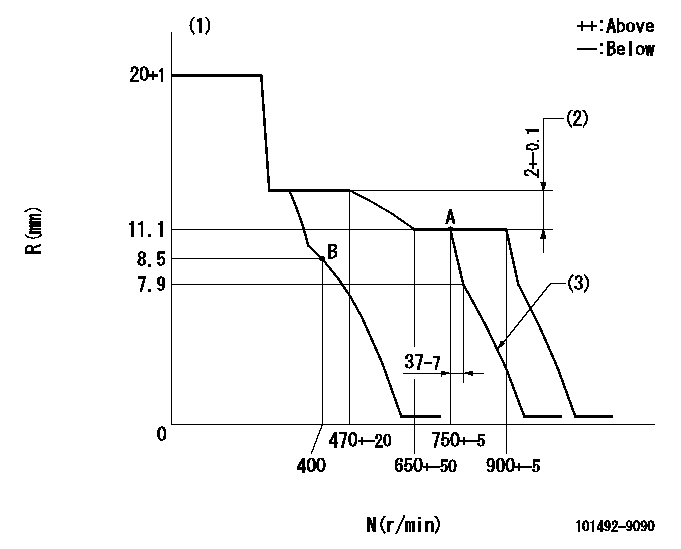
N:Pump speed
R:Rack position (mm)
(1)Target notch: K
(2)Rack difference between N = N1 and N = N2
(3)Idle sub spring setting: L1.
----------
K=8 N1=750r/min N2=400r/min L1=7.9-0.5mm
----------
----------
K=8 N1=750r/min N2=400r/min L1=7.9-0.5mm
----------
Speed control lever angle
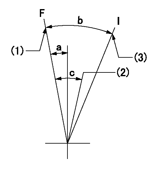
F:Full speed
I:Idle
(1)Set the pump speed at aa. ( At delivery )
(2)Set the pump speed at bb.
(3)Stopper bolt setting
----------
aa=900r/min bb=750r/min
----------
a=(4deg)+-5deg b=(22deg)+-5deg c=(6deg)+-5deg
----------
aa=900r/min bb=750r/min
----------
a=(4deg)+-5deg b=(22deg)+-5deg c=(6deg)+-5deg
Stop lever angle

N:Pump normal
S:Stop the pump.
----------
----------
a=26.5deg+-5deg b=53deg+-5deg
----------
----------
a=26.5deg+-5deg b=53deg+-5deg
0000001501 GOV FULL LOAD ADJUSTMENT
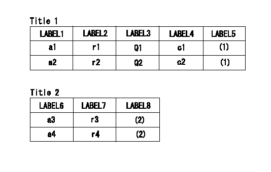
Title1:Full load stopper adjustment
Title2:Governor set speed
LABEL1:Distinguishing
LABEL2:Pump speed (r/min)
LABEL3:Ave. injection quantity (mm3/st)
LABEL4:Max. var. bet. cyl.
LABEL5:Remarks
LABEL6:Distinguishing
LABEL7:Governor set speed (r/min)
LABEL8:Remarks
(1)Adjustment conditions are the same as those for measuring injection quantity.
(2)-
----------
----------
a1=A a2=- r1=750r/min r2=- Q1=44.7+-1mm3/st Q2=- c1=+-3.5% c2=- a3=18 a4=15 r3=900r/min r4=750r/min
----------
----------
a1=A a2=- r1=750r/min r2=- Q1=44.7+-1mm3/st Q2=- c1=+-3.5% c2=- a3=18 a4=15 r3=900r/min r4=750r/min
Timing setting

(1)Pump vertical direction
(2)Position of gear's standard threaded hole (position of gear mark 'N') at No 1 cylinder's beginning of injection
(3)-
(4)-
----------
----------
a=(60deg)
----------
----------
a=(60deg)
Information:
ACTION REQUIRED
1. Refer to Special Instruction, REHS5023, "Replacing the Fuel Injection Pump on Certain C9.3 Engines". Replace the existing 375-5244 or early production 379-0150 common rail fuel injection pump with the new production 379-0150 common rail fuel injection pump and new gasket 6V-8260. Install a new 356-5214 fuel line from the common rail fuel injection pump to the fuel rail.
2. Refer to C9.3 Disassembly and Assembly, KENR8149 "Engines for Caterpillar Built Machines". Replace the prior 362-0770 Pressure Relief Valve with 415-4991 Pressure Relief Valve, and 228-7102 O-ring.
3. Refer to Service Magazine, SEPD1928, "An Improved Fuel Injection Pump Group Is Used on Certain C9.3 Machine Engines", in order to record the common rail fuel injection pump serial number. This serial number must be entered into the containment service letter claim story.
SERVICE CLAIM ALLOWANCES
Product smu/age whichever comes first Caterpillar Dealer Suggested Customer Suggested
Parts % Labor Hrs% Parts % Labor Hrs% Parts % Labor Hrs%
*******Group 1*******
0-5000 hrs,
0-48 mo 100.0% 100.0% 0.0% 0.0% 0.0% 0.0%
This is a 12.0-hour job for Group 1
Product smu/age whichever comes first Caterpillar Dealer Suggested Customer Suggested
Parts % Labor Hrs% Parts % Labor Hrs% Parts % Labor Hrs%
*******Group 2*******
0-5000 hrs,
0-48 mo 100.0% 100.0% 0.0% 0.0% 0.0% 0.0%
This is a 18.0-hour job for Group 2
Product smu/age whichever comes first Caterpillar Dealer Suggested Customer Suggested
Parts % Labor Hrs% Parts % Labor Hrs% Parts % Labor Hrs%
*******Group 3*******
0-5000 hrs,
0-48 mo 100.0% 100.0% 0.0% 0.0% 0.0% 0.0%
This is a 15.0-hour job for Group 3
PARTS DISPOSITION
Handle the parts in accordance with your Warranty Bulletin on warranty parts handling.