Information injection-pump assembly
BOSCH
9 400 614 469
9400614469
ZEXEL
101492-9080
1014929080
NISSAN-DIESEL
1679090210
1679090210

Rating:
Service parts 101492-9080 INJECTION-PUMP ASSEMBLY:
1.
_
5.
AUTOM. ADVANCE MECHANIS
6.
COUPLING PLATE
8.
_
9.
_
11.
Nozzle and Holder
16600T9303
12.
Open Pre:MPa(Kqf/cm2)
19.6(200)
14.
NOZZLE
15.
NOZZLE SET
Cross reference number
BOSCH
9 400 614 469
9400614469
ZEXEL
101492-9080
1014929080
NISSAN-DIESEL
1679090210
1679090210
Zexel num
Bosch num
Firm num
Name
101492-9080
9 400 614 469
1679090210 NISSAN-DIESEL
INJECTION-PUMP ASSEMBLY
FD33 K 14BC INJECTION PUMP ASSY PE4A,5A, PE
FD33 K 14BC INJECTION PUMP ASSY PE4A,5A, PE
Calibration Data:
Adjustment conditions
Test oil
1404 Test oil ISO4113 or {SAEJ967d}
1404 Test oil ISO4113 or {SAEJ967d}
Test oil temperature
degC
40
40
45
Nozzle and nozzle holder
105780-8140
Bosch type code
EF8511/9A
Nozzle
105780-0000
Bosch type code
DN12SD12T
Nozzle holder
105780-2080
Bosch type code
EF8511/9
Opening pressure
MPa
17.2
Opening pressure
kgf/cm2
175
Injection pipe
Outer diameter - inner diameter - length (mm) mm 6-2-600
Outer diameter - inner diameter - length (mm) mm 6-2-600
Overflow valve
131424-6120
Overflow valve opening pressure
kPa
191
157
225
Overflow valve opening pressure
kgf/cm2
1.95
1.6
2.3
Tester oil delivery pressure
kPa
157
157
157
Tester oil delivery pressure
kgf/cm2
1.6
1.6
1.6
Direction of rotation (viewed from drive side)
Right R
Right R
Injection timing adjustment
Direction of rotation (viewed from drive side)
Right R
Right R
Injection order
1-3-4-2
Pre-stroke
mm
3.4
3.35
3.45
Beginning of injection position
Drive side NO.1
Drive side NO.1
Difference between angles 1
Cal 1-3 deg. 90 89.5 90.5
Cal 1-3 deg. 90 89.5 90.5
Difference between angles 2
Cal 1-4 deg. 180 179.5 180.5
Cal 1-4 deg. 180 179.5 180.5
Difference between angles 3
Cyl.1-2 deg. 270 269.5 270.5
Cyl.1-2 deg. 270 269.5 270.5
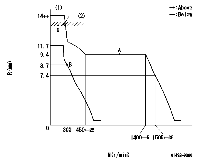
Injection quantity adjustment
Adjusting point
A
Rack position
9.4
Pump speed
r/min
1000
1000
1000
Average injection quantity
mm3/st.
40.9
39.9
41.9
Max. variation between cylinders
%
0
-3.5
3.5
Basic
*
Fixing the lever
*
Injection quantity adjustment_02
Adjusting point
B
Rack position
8.7+-0.5
Pump speed
r/min
300
300
300
Average injection quantity
mm3/st.
8.2
6.2
10.2
Max. variation between cylinders
%
0
-10
10
Fixing the rack
*
Injection quantity adjustment_03
Adjusting point
C
Rack position
13.9+-0.
5
Pump speed
r/min
100
100
100
Average injection quantity
mm3/st.
65
65
75
Fixing the lever
*
Rack limit
*
Test data Ex:
Governor adjustment
N:Pump speed
R:Rack position (mm)
(1)Target notch: K
(2)RACK LIMIT
----------
K=17
----------
----------
K=17
----------
Speed control lever angle

F:Full speed
I:Idle
(1)Stopper bolt setting
----------
----------
a=24deg+-5deg b=25deg+-5deg
----------
----------
a=24deg+-5deg b=25deg+-5deg
Stop lever angle

N:Pump normal
S:Stop the pump.
----------
----------
a=26.5deg+-5deg b=53deg+-5deg
----------
----------
a=26.5deg+-5deg b=53deg+-5deg
0000001501 GOV FULL LOAD ADJUSTMENT

Title1:Full load stopper adjustment
Title2:Governor set speed
LABEL1:Distinguishing
LABEL2:Pump speed (r/min)
LABEL3:Ave. injection quantity (mm3/st)
LABEL4:Max. var. bet. cyl.
LABEL5:Remarks
LABEL6:Distinguishing
LABEL7:Governor set speed (r/min)
LABEL8:Maximum no-load speed (r/min)
LABEL9:Remarks
(1)Adjustment conditions are the same as those for measuring injection quantity.
(2)At high idle rack position L
----------
L=7.4mm
----------
a1=A a2=B a3=C a4=D r1=1000r/min r2=1000r/min r3=1000r/min r4=- Q1=43.5+-1mm3/st Q2=40.9+-1mm3/st Q3=39.6+-1mm3/st Q4=- c1=+-3.5% c2=+-3.5% c3=+-3.5% c4=- a5=28 a6=27 a7=26 a8=25 a9=24 a10=23 a11=22 a12=21 a13=20 a14=19 a15=18 r5=1400r/min r6=1350r/min r7=1300r/min r8=1250r/min r9=1200r/min r10=1150r/min r11=1100r/min r12=1050r/min r13=1000r/min r14=950r/min r15=900r/min R5=1505+-35r/min R6=1450+-33r/min R7=1395+-32r/min R8=1340+-31r/min R9=1290+-30r/min R10=1235+-28r/min R11=1180+-27r/min R12=1130+-26r/min R13=1075+-25r/min R14=1020+-23r/min R15=965+-22r/min
----------
L=7.4mm
----------
a1=A a2=B a3=C a4=D r1=1000r/min r2=1000r/min r3=1000r/min r4=- Q1=43.5+-1mm3/st Q2=40.9+-1mm3/st Q3=39.6+-1mm3/st Q4=- c1=+-3.5% c2=+-3.5% c3=+-3.5% c4=- a5=28 a6=27 a7=26 a8=25 a9=24 a10=23 a11=22 a12=21 a13=20 a14=19 a15=18 r5=1400r/min r6=1350r/min r7=1300r/min r8=1250r/min r9=1200r/min r10=1150r/min r11=1100r/min r12=1050r/min r13=1000r/min r14=950r/min r15=900r/min R5=1505+-35r/min R6=1450+-33r/min R7=1395+-32r/min R8=1340+-31r/min R9=1290+-30r/min R10=1235+-28r/min R11=1180+-27r/min R12=1130+-26r/min R13=1075+-25r/min R14=1020+-23r/min R15=965+-22r/min
Timing setting

(1)Pump vertical direction
(2)Position of gear's standard threaded hole (position of gear mark 'N') at No 1 cylinder's beginning of injection
(3)-
(4)-
----------
----------
a=(60deg)
----------
----------
a=(60deg)
Information:
Caterpillar’s obligations under this Service Letter are subject to, and shall not apply in contravention of, the laws, rules, regulations, directives, ordinances, orders, or statutes of the United States, or of any other applicable jurisdiction, without recourse or liability with respect to Caterpillar.
This Program must be administered either before or after failure.In either case the decision whether to apply the Program is made by the dealer. When reporting the repair, use "PS44681" as the Part Numberand "7755" as the Group Number. If administered before failure, use "56" as the Warranty Claim Description Code and "T" as the SIMS Description code.If administered after failure, use "96" as the Warranty Claim Description Code, and "Z" as the SIMS Description Code.
The information supplied in this service letter may not be valid after the termination date of this program.Do not perform the work outlined in this Service Letter after the termination date without first contacting your Caterpillar product analyst.
TERMINATION DATE
31Mar2017
PROBLEM
The existing injectors can misfire on certain D7R Track-Type Tractors. If the existing injectors fail it can cause the poppet valve seizure in the injector.
AFFECTED PRODUCT
Model Identification Number
D7R II KNA00214-00217, 219-781
PARTS NEEDED
Qty
Part Number Description
6 20R0055 INJECTOR GP-FUEL
In order to allow equitable parts availability to all participating dealers, please limit your initial parts order to not exceed 28% of dealership population. This is an initial order recommendation only, and the ultimate responsibility for ordering the total number of parts needed to satisfy the program lies with the dealer.
ACTION REQUIRED
Replace all six injectors. Reference the Disassembly and Assembly Manual for service instructions.
SERVICE CLAIM ALLOWANCES
Product smu/age whichever comes first Caterpillar Dealer Suggested Customer Suggested
Parts % Labor Hrs% Parts % Labor Hrs% Parts % Labor Hrs%
0-5000 hrs,
0-48 mo 100.0% 100.0% 0.0% 0.0% 0.0% 0.0%
This is a 6.0-hour job
If necessary, reasonable Travel Time and Mileage is allowed.
PARTS DISPOSITION
Handle the parts in accordance with your Warranty Bulletin on warranty parts handling.
Have questions with 101492-9080?
Group cross 101492-9080 ZEXEL
Nissan-Diesel
101492-9080
9 400 614 469
1679090210
INJECTION-PUMP ASSEMBLY
FD33
FD33