Information injection-pump assembly
BOSCH
9 400 614 465
9400614465
ZEXEL
101492-4032
1014924032
ISUZU
8972306202
8972306202
Rating:
Include in #1:
106682-4970
as _
Cross reference number
BOSCH
9 400 614 465
9400614465
ZEXEL
101492-4032
1014924032
ISUZU
8972306202
8972306202
Zexel num
Bosch num
Firm num
Name
101492-4032
9 400 614 465
8972306202 ISUZU
INJECTION-PUMP ASSEMBLY
4JG1 K 14BC INJECTION PUMP ASSY PE4A,5A, PE
4JG1 K 14BC INJECTION PUMP ASSY PE4A,5A, PE
Calibration Data:
Adjustment conditions
Test oil
1404 Test oil ISO4113 or {SAEJ967d}
1404 Test oil ISO4113 or {SAEJ967d}
Test oil temperature
degC
40
40
45
Nozzle and nozzle holder
105780-8140
Bosch type code
EF8511/9A
Nozzle
105780-0000
Bosch type code
DN12SD12T
Nozzle holder
105780-2080
Bosch type code
EF8511/9
Opening pressure
MPa
17.2
Opening pressure
kgf/cm2
175
Injection pipe
Outer diameter - inner diameter - length (mm) mm 6-2-600
Outer diameter - inner diameter - length (mm) mm 6-2-600
Overflow valve
131424-0820
Overflow valve opening pressure
kPa
127
107
147
Overflow valve opening pressure
kgf/cm2
1.3
1.1
1.5
Tester oil delivery pressure
kPa
157
157
157
Tester oil delivery pressure
kgf/cm2
1.6
1.6
1.6
Direction of rotation (viewed from drive side)
Left L
Left L
Injection timing adjustment
Direction of rotation (viewed from drive side)
Left L
Left L
Injection order
1-3-4-2
Pre-stroke
mm
2.6
2.55
2.65
Beginning of injection position
Drive side NO.1
Drive side NO.1
Difference between angles 1
Cal 1-3 deg. 90 89.5 90.5
Cal 1-3 deg. 90 89.5 90.5
Difference between angles 2
Cal 1-4 deg. 180 179.5 180.5
Cal 1-4 deg. 180 179.5 180.5
Difference between angles 3
Cyl.1-2 deg. 270 269.5 270.5
Cyl.1-2 deg. 270 269.5 270.5
Injection quantity adjustment
Adjusting point
A
Rack position
8.4
Pump speed
r/min
1050
1050
1050
Average injection quantity
mm3/st.
57.5
56.5
58.5
Max. variation between cylinders
%
0
-2.5
2.5
Basic
*
Fixing the lever
*
Injection quantity adjustment_02
Adjusting point
-
Rack position
6.5+-0.5
Pump speed
r/min
540
540
540
Average injection quantity
mm3/st.
11.5
9.5
13.5
Max. variation between cylinders
%
0
-15
15
Fixing the rack
*
Remarks
Adjust only variation between cylinders; adjust governor according to governor specifications.
Adjust only variation between cylinders; adjust governor according to governor specifications.
Injection quantity adjustment_03
Adjusting point
D
Rack position
8.6++
Pump speed
r/min
100
100
100
Average injection quantity
mm3/st.
95
90
100
Fixing the lever
*
Rack limit
*
Test data Ex:
Governor adjustment
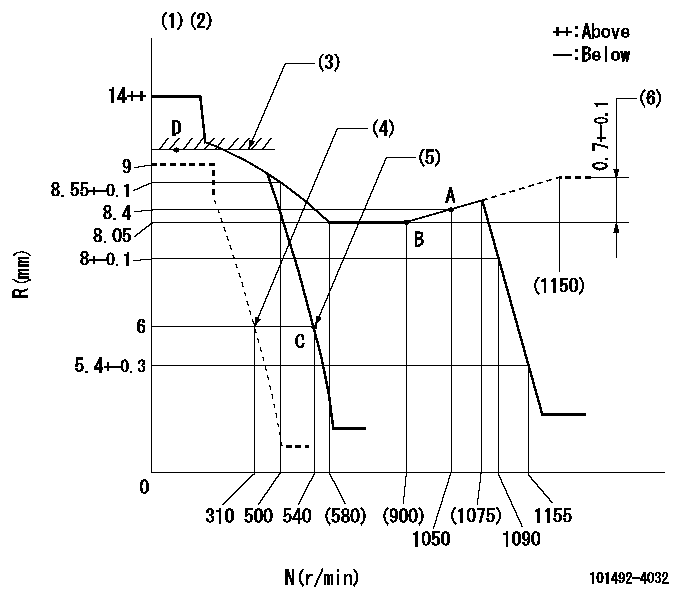
N:Pump speed
R:Rack position (mm)
(1)Target notch: K
(2)Tolerance for racks not indicated: +-0.05mm.
(3)RACK LIMIT
(4)Set idle sub-spring
(5)Main spring setting
(6)Rack difference between N = N1 and N = N2
----------
K=8 N1=1200r/min N2=740r/min
----------
----------
K=8 N1=1200r/min N2=740r/min
----------
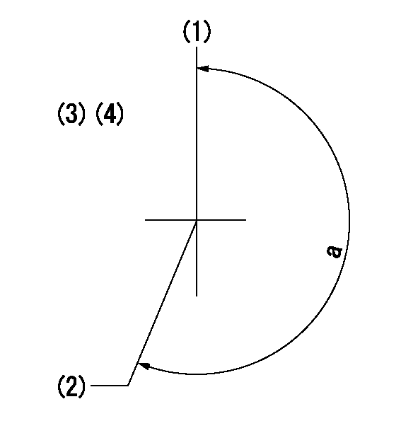
Speed control lever angle
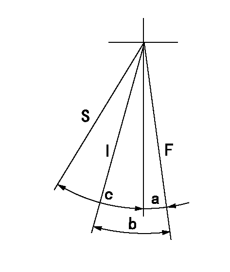
F:Full speed
I:Idle
S:Stop
----------
----------
a=(3deg)+-5deg b=(17deg)+-5deg c=31deg+-3deg
----------
----------
a=(3deg)+-5deg b=(17deg)+-5deg c=31deg+-3deg
Stop lever angle
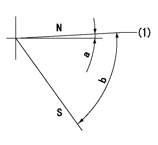
N:Pump normal
S:Stop the pump.
(1)Normal
----------
----------
a=0deg+-5deg b=53deg+-5deg
----------
----------
a=0deg+-5deg b=53deg+-5deg
Timing setting
(1)Pump vertical direction
(2)Position of gear mark 'W' at No 1 cylinder's beginning of injection
(3)B.T.D.C.: aa
(4)-
----------
aa=10deg
----------
a=(210deg)
----------
aa=10deg
----------
a=(210deg)
Information:
PROBLEM
The Diesel Particulate Filter core may fail on certain C3.4B Industrial Engines. The failures may result in loss of power and a blocked Diesel Particulate Filter.
AFFECTED PRODUCT
Model Identification Number
C3.4B CJG01859-01865, 1867, 1869-1870, 1901-1910, 1994, 2268, 2272, 2323-2324, 2364-2365, 2367-2374, 2376-2377, 2414, 2430-2439, 2441-2446, 2454-2456, 2458-2460, 2462-2463, 2482, 2529, 4411-4414, 4453-4465, 4999-5025, 5048-5050, 5069-5088, 5090-5095
CNW00578-00579, 581-587, 666, 668-674, 677, 680, 684, 708, 730-738, 740-744, 746, 748-750
PARTS NEEDED
Qty
Part Number Description
1 20R3615 KIT-FILTER (After Failure Only)
1 3793061 SEAL (After Failure Only)
1 3793064 SEAL-O-RING (After Failure Only)
1 3879343 CLIP (After Failure Only)
1 4732321 ENGINE SOFTWARE
1 4813598 FILTER AS (After Failure Only)
1 GND_WIRE_KIT Regen Interlock GND Wire Kit (See Action Required)
In order to allow equitable parts availability to all participating dealers, please limit your initial parts order to not exceed 26% of dealership population. This is an initial order recommendation only, and the ultimate responsibility for ordering the total number of parts needed to satisfy the program lies with the dealer.
ACTION REQUIRED
Before Failure:
1 - Update Engine Software, refer to Troubleshooting ? ECM Software ? Install, ensure to follow the steps to save the Engine Configuration data.
2 - Apply Carlson Service Number 14CP-013 - Regeneration Interlock Ground Wire Kit, contact a Carlson Paving Products Dealer for Kit Part Number 14CP-013.
After Failure:
1 - Refer to Steps 1 and 2 of the Before Failure actions.
2 - Service CCB Filter and replace with new filter, refer to Operation and Maintenance Manual ? Engine Crankcase Breather element ? Replace.
3 - Remove Diesel Particulate Filter, Refer to Disassembly and Assembly - Diesel Particulate Filter - Remove - wall Flow Diesel Particulate Filter.
4 - Move the Diesel Particulate Filter Assembly to a suitable work surface.
5 - Refer to Specifications - Diesel Particulate Filter (Wall Flow Diesel Particulate Filter(DPF)), remove V Band Clamps (1) and (4), carefully split assembly and remove DPF Canister element.
6 - Using new DPF Kit Filter, reassemble the Diesel Particulate Filter Assembly noting the alignment marks previously made in Step 3, refer to Specifications - Diesel Particulate Filter (Wall Flow Diesel Particulate Filter(DPF)).
7 - Reinstall the Diesel Particulate Filter assembly, Refer to Disassembly and Assembly - Diesel Particulate Filter - Install - wall Flow Diesel Particulate Filter.
8 - As the DPF has been replaced, ensure the ?DPF Replacement Reset? procedure is performed using CAT ET, refer to Troubleshooting - Service Tool Features - Components Replacement Resets.
SERVICE CLAIM ALLOWANCES
Product smu/age whichever comes first Caterpillar Dealer Suggested Customer Suggested
Parts % Labor Hrs% Parts % Labor Hrs% Parts % Labor Hrs%
0-5000 hrs,
0-60 mo 100.0% 100.0% 0.0% 0.0% 0.0% 0.0%
This is a 1.5-hour job
Note an additional 4.5 hours is allowed for After Failure.
PARTS DISPOSITION
Handle the parts in accordance with your Warranty Bulletin on warranty parts handling.
Have questions with 101492-4032?
Group cross 101492-4032 ZEXEL
Isuzu
101492-4032
9 400 614 465
8972306202
INJECTION-PUMP ASSEMBLY
4JG1
4JG1