Information injection-pump assembly
ZEXEL
101492-3860
1014923860
KOMATSU
6205711233
6205711233
Rating:
Cross reference number
ZEXEL
101492-3860
1014923860
KOMATSU
6205711233
6205711233
Zexel num
Bosch num
Firm num
Name
101492-3860
6205711233 KOMATSU
INJECTION-PUMP ASSEMBLY
S4D95L * K
S4D95L * K
Calibration Data:
Adjustment conditions
Test oil
1404 Test oil ISO4113 or {SAEJ967d}
1404 Test oil ISO4113 or {SAEJ967d}
Test oil temperature
degC
40
40
45
Nozzle and nozzle holder
105780-8140
Bosch type code
EF8511/9A
Nozzle
105780-0000
Bosch type code
DN12SD12T
Nozzle holder
105780-2080
Bosch type code
EF8511/9
Opening pressure
MPa
17.2
Opening pressure
kgf/cm2
175
Injection pipe
Outer diameter - inner diameter - length (mm) mm 6-2-600
Outer diameter - inner diameter - length (mm) mm 6-2-600
Overflow valve
131424-7420
Overflow valve opening pressure
kPa
255
221
289
Overflow valve opening pressure
kgf/cm2
2.6
2.25
2.95
Tester oil delivery pressure
kPa
157
157
157
Tester oil delivery pressure
kgf/cm2
1.6
1.6
1.6
Direction of rotation (viewed from drive side)
Right R
Right R
Injection timing adjustment
Direction of rotation (viewed from drive side)
Right R
Right R
Injection order
1-2-4-3
Pre-stroke
mm
3.2
3.15
3.25
Beginning of injection position
Drive side NO.1
Drive side NO.1
Difference between angles 1
Cyl.1-2 deg. 90 89.5 90.5
Cyl.1-2 deg. 90 89.5 90.5
Difference between angles 2
Cal 1-4 deg. 180 179.5 180.5
Cal 1-4 deg. 180 179.5 180.5
Difference between angles 3
Cal 1-3 deg. 270 269.5 270.5
Cal 1-3 deg. 270 269.5 270.5
Injection quantity adjustment
Adjusting point
A
Rack position
9.7
Pump speed
r/min
1050
1050
1050
Average injection quantity
mm3/st.
67.7
66.7
68.7
Max. variation between cylinders
%
0
-2.5
2.5
Basic
*
Fixing the lever
*
Injection quantity adjustment_02
Adjusting point
-
Rack position
7.7+-0.5
Pump speed
r/min
450
450
450
Average injection quantity
mm3/st.
10.5
9.5
11.5
Max. variation between cylinders
%
0
-15
15
Fixing the rack
*
Remarks
Adjust only variation between cylinders; adjust governor according to governor specifications.
Adjust only variation between cylinders; adjust governor according to governor specifications.
Test data Ex:
Governor adjustment
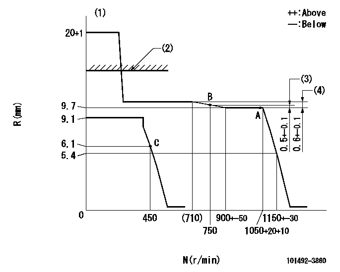
N:Pump speed
R:Rack position (mm)
(1)Target notch: K
(2)RACK LIMIT: RAL
(3)Rack difference from N = N1
(4)Rack difference between N = N2 and N = N3
----------
K=14 RAL=12.5+0.2mm N1=1050r/min N2=1050r/min N3=500r/min
----------
----------
K=14 RAL=12.5+0.2mm N1=1050r/min N2=1050r/min N3=500r/min
----------
Speed control lever angle
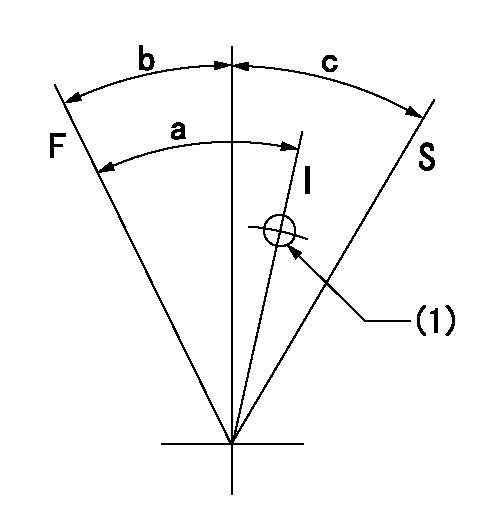
F:Full speed
I:Idle
S:Stop
(1)Use the hole at R = aa
----------
aa=80mm
----------
a=32deg+-5deg b=16deg+-3deg c=32deg+-3deg
----------
aa=80mm
----------
a=32deg+-5deg b=16deg+-3deg c=32deg+-3deg
Timing setting

(1)Pump vertical direction
(2)Position of key groove at No 1 cylinder's beginning of injection
(3)Stamp aligning marks on the pump housing flange.
(4)-
(5)-
----------
----------
a=58deg+-3deg b=2deg+-30min
----------
----------
a=58deg+-3deg b=2deg+-30min
Information:
ACTION REQUIRED
Replace cylinder head, reusing cylinder head bolts and washers after performing visual inspection. Reinstall injector, injector return line, and quill tube with new injector seals, injector return line seals, and quill tube bolts. Reference KENR6052 for removal and installation procedures and for troubleshooting guidance on diagnosing a leaking injector sleeve refer to the info below.
If the source of the sodium cannot be isolated via other normal testing of individual components (water pumps, oil coolers, etc.) then complete the following procedure:
1. Shut down the engine and allow system to cool.
2. Flip the ground level shutdown switch on the truck front bumper and leave the switch engaged. This action disables the fuel injection.
3. Verify that the engine will crank but the engine does NOT start.
4. Pull the last exhaust manifold from each bank of the engine.
5. Pressurize the truck cooling system, refer to Testing and Adjusting, KENR5397 for additional information.
6. Hold pressure on the cooling system for no more than 10 minutes for the first test. If the leak is bad, holding the pressure too long could risk hydraulic lock.
7. While cranking the engine, shine a light up into the exhaust manifolds and look for cylinders that are puffing steam and white smoke. Refer to Image 1.
8. Verify any leaks by pulling the exhaust thermocouple port from the exhaust runner on that cylinder. Check for signs of moisture/steaming in that exhaust runner.
9. Repair any leaking injector sleeve by replacing the head.
Image1
SERVICE CLAIM ALLOWANCES
Product smu/age whichever comes first Caterpillar Dealer Suggested Customer Suggested
Parts % Labor Hrs% Parts % Labor Hrs% Parts % Labor Hrs%
0-9000 hrs,
0-24 mo 100.0% 100.0% 0.0% 0.0% 0.0% 0.0%
9001-18000 hrs,
25-48 mo 33.0% 50.0% 0.0% 0.0% 50.0% 50.0%
This is a 8.0-hour job
If there has been a previous repair, part age/hours will apply. Retain a copy of the previous repair invoice in the dealer's records for audit purposes, and specify repair date and machine hours in the "Additional Comments" section of the warranty claim.
The 8 hour labor allowance consists of:
4 hours troubleshooting max per repair
4 hours repair time
If more than one cylinder has failed, an additional 4 hours repair time per additional cylinder is allowed. Repairing up to 4 cylinders (793F) and 6 cylinders (797B, 797F) in chassis is allowed. No additional troubleshooting time is allowed.
PARTS DISPOSITION
Handle the parts in accordance with your Warranty Bulletin on warranty parts handling.
Have questions with 101492-3860?
Group cross 101492-3860 ZEXEL
Komatsu
101492-3860
6205711233
INJECTION-PUMP ASSEMBLY
S4D95L
S4D95L