Information injection-pump assembly
BOSCH
9 400 613 360
9400613360
ZEXEL
101492-3830
1014923830
KOMATSU
6205711270
6205711270
Rating:
Service parts 101492-3830 INJECTION-PUMP ASSEMBLY:
1.
_
5.
AUTOM. ADVANCE MECHANIS
6.
COUPLING PLATE
7.
COUPLING PLATE
8.
_
9.
_
11.
Nozzle and Holder
6206-11-3100
12.
Open Pre:MPa(Kqf/cm2)
19.6{200}
15.
NOZZLE SET
Cross reference number
BOSCH
9 400 613 360
9400613360
ZEXEL
101492-3830
1014923830
KOMATSU
6205711270
6205711270
Zexel num
Bosch num
Firm num
Name
9 400 613 360
6205711270 KOMATSU
INJECTION-PUMP ASSEMBLY
S4D95L K 14BC INJECTION PUMP ASSY PE4A,5A, PE
S4D95L K 14BC INJECTION PUMP ASSY PE4A,5A, PE
Calibration Data:
Adjustment conditions
Test oil
1404 Test oil ISO4113 or {SAEJ967d}
1404 Test oil ISO4113 or {SAEJ967d}
Test oil temperature
degC
40
40
45
Nozzle and nozzle holder
105780-8140
Bosch type code
EF8511/9A
Nozzle
105780-0000
Bosch type code
DN12SD12T
Nozzle holder
105780-2080
Bosch type code
EF8511/9
Opening pressure
MPa
17.2
Opening pressure
kgf/cm2
175
Injection pipe
Outer diameter - inner diameter - length (mm) mm 6-2-600
Outer diameter - inner diameter - length (mm) mm 6-2-600
Overflow valve
131424-7420
Overflow valve opening pressure
kPa
255
221
289
Overflow valve opening pressure
kgf/cm2
2.6
2.25
2.95
Tester oil delivery pressure
kPa
157
157
157
Tester oil delivery pressure
kgf/cm2
1.6
1.6
1.6
Direction of rotation (viewed from drive side)
Right R
Right R
Injection timing adjustment
Direction of rotation (viewed from drive side)
Right R
Right R
Injection order
1-2-4-3
Pre-stroke
mm
3.2
3.15
3.25
Rack position
Point A R=A
Point A R=A
Beginning of injection position
Drive side NO.1
Drive side NO.1
Difference between angles 1
Cyl.1-2 deg. 90 89.5 90.5
Cyl.1-2 deg. 90 89.5 90.5
Difference between angles 2
Cal 1-4 deg. 180 179.5 180.5
Cal 1-4 deg. 180 179.5 180.5
Difference between angles 3
Cal 1-3 deg. 270 269.5 270.5
Cal 1-3 deg. 270 269.5 270.5
Injection quantity adjustment
Adjusting point
A
Rack position
9.7
Pump speed
r/min
1050
1050
1050
Average injection quantity
mm3/st.
67.7
66.7
68.7
Max. variation between cylinders
%
0
-2.5
2.5
Basic
*
Fixing the lever
*
Injection quantity adjustment_02
Adjusting point
-
Rack position
7.7+-0.5
Pump speed
r/min
450
450
450
Average injection quantity
mm3/st.
10.5
9.5
11.5
Max. variation between cylinders
%
0
-15
15
Fixing the rack
*
Remarks
Adjust only variation between cylinders; adjust governor according to governor specifications.
Adjust only variation between cylinders; adjust governor according to governor specifications.
Test data Ex:
Governor adjustment
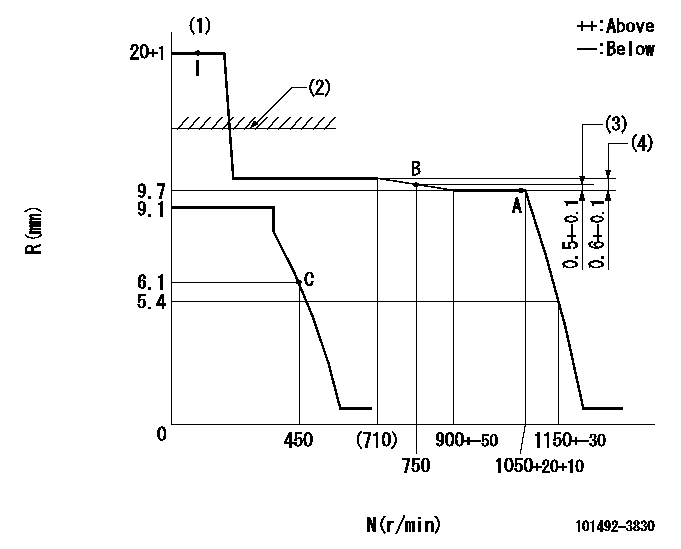
N:Pump speed
R:Rack position (mm)
(1)Target notch: K
(2)RACK CAP: R1
(3)Rack difference from N = N1
(4)Rack difference between N = N2 and N = N3
----------
K=14 R1=15+-1mm N1=1050r/min N2=1050r/min N3=500r/min
----------
----------
K=14 R1=15+-1mm N1=1050r/min N2=1050r/min N3=500r/min
----------
Speed control lever angle
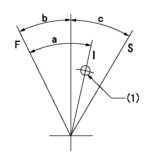
F:Full speed
I:Idle
S:Stop
(1)Use the hole at R = aa
----------
aa=80mm
----------
a=32deg+-5deg b=16deg+-3deg c=32deg+-3deg
----------
aa=80mm
----------
a=32deg+-5deg b=16deg+-3deg c=32deg+-3deg
Timing setting
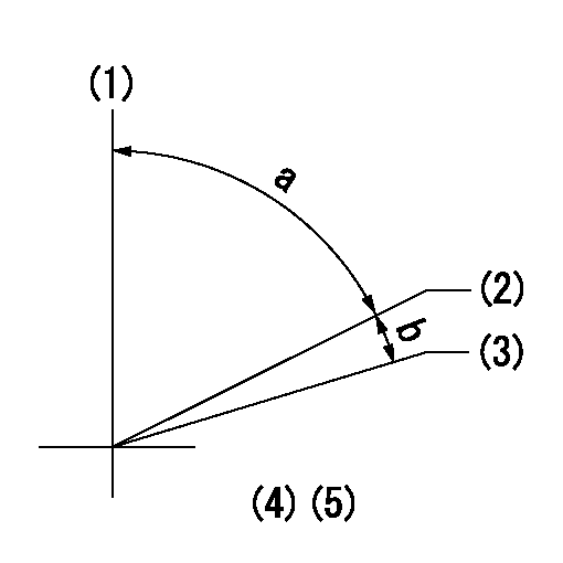
(1)Pump vertical direction
(2)Position of key groove at No 1 cylinder's beginning of injection
(3)Stamp aligning marks on the pump housing flange.
(4)-
----------
----------
a=58deg+-3deg b=2deg+-30min
----------
----------
a=58deg+-3deg b=2deg+-30min
Information:
21Mar2016
U-141
A-108
D-125
O-121
Parts stock action only
PRODUCT IMPROVEMENT PROGRAM FOR REMOVING CERTAIN 341-2378 INJECTOR WIRING HARNESSES FROM DEALER PART STOCK
1408 7750 PI70613
Caterpillar’s obligations under this Service Letter are subject to, and shall not apply in contravention of, the laws, rules, regulations, directives, ordinances, orders, or statutes of the United States, or of any other applicable jurisdiction, without recourse or liability with respect to Caterpillar.
When submitting claim for Parts Stock Action, Use the appropriate 99Z as the s/n, the appropriate Service Letter Program Number as the Part number in the Part Causing Failure field, "7751" as the Group Number, "56" as the Description Code.
The information supplied in this service letter may not be valid after the termination date of this program.Do not perform the work outlined in this Service Letter after the termination date without first contacting your Caterpillar product analyst.
TERMINATION DATE
30Jun2016
PROBLEM
The 341-2378 Injector Wiring Harness may cause an intermittent injector signal that may cause an injector diagnostic code. The manufacturing process has been improved.
ACTION REQUIRED
Known good 341-2378 Injector Wiring Harnesses have a blue tie strap around the harness, and have been manufactured with an improved process. Do not remove a harness that has a blue tie strap around the wiring harness from dealer parts stock.
Remove all 341-2378 Injector Wiring Harnesses manufactured without a blue tie strap attached to the wiring harness from dealer parts stock.
Image 1 shows the harness with a blue tie strap on the braid.
Image1
SERVICE CLAIM ALLOWANCES
Submit one claim for all parts removed from dealer parts stock.
PARTS DISPOSITION
Handle the parts in accordance with your Warranty Bulletin on warranty parts handling.
