Information injection-pump assembly
ZEXEL
101492-3690
1014923690

Rating:
Cross reference number
ZEXEL
101492-3690
1014923690
Zexel num
Bosch num
Firm num
Name
Calibration Data:
Adjustment conditions
Test oil
1404 Test oil ISO4113 or {SAEJ967d}
1404 Test oil ISO4113 or {SAEJ967d}
Test oil temperature
degC
40
40
45
Nozzle and nozzle holder
105780-8140
Bosch type code
EF8511/9A
Nozzle
105780-0000
Bosch type code
DN12SD12T
Nozzle holder
105780-2080
Bosch type code
EF8511/9
Opening pressure
MPa
17.2
Opening pressure
kgf/cm2
175
Injection pipe
Outer diameter - inner diameter - length (mm) mm 6-2-600
Outer diameter - inner diameter - length (mm) mm 6-2-600
Overflow valve
132424-0620
Overflow valve opening pressure
kPa
157
123
191
Overflow valve opening pressure
kgf/cm2
1.6
1.25
1.95
Tester oil delivery pressure
kPa
157
157
157
Tester oil delivery pressure
kgf/cm2
1.6
1.6
1.6
Direction of rotation (viewed from drive side)
Right R
Right R
Injection timing adjustment
Direction of rotation (viewed from drive side)
Right R
Right R
Injection order
1-2-4-3
Pre-stroke
mm
3.6
3.55
3.65
Rack position
Point A R=A
Point A R=A
Beginning of injection position
Drive side NO.1
Drive side NO.1
Difference between angles 1
Cyl.1-2 deg. 90 89.5 90.5
Cyl.1-2 deg. 90 89.5 90.5
Difference between angles 2
Cal 1-4 deg. 180 179.5 180.5
Cal 1-4 deg. 180 179.5 180.5
Difference between angles 3
Cal 1-3 deg. 270 269.5 270.5
Cal 1-3 deg. 270 269.5 270.5
Injection quantity adjustment
Adjusting point
A
Rack position
11.2
Pump speed
r/min
950
950
950
Average injection quantity
mm3/st.
43.9
42.9
44.9
Max. variation between cylinders
%
0
-2.5
2.5
Basic
*
Fixing the lever
*
Injection quantity adjustment_02
Adjusting point
-
Rack position
10+-0.5
Pump speed
r/min
450
450
450
Average injection quantity
mm3/st.
10.5
9.5
11.5
Max. variation between cylinders
%
0
-15
15
Fixing the rack
*
Remarks
Adjust only variation between cylinders; adjust governor according to governor specifications.
Adjust only variation between cylinders; adjust governor according to governor specifications.
Test data Ex:
Governor adjustment
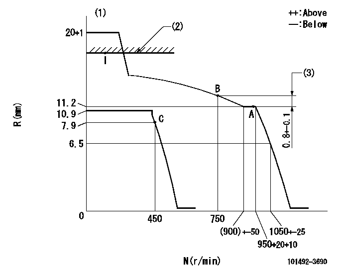
N:Pump speed
R:Rack position (mm)
(1)Target notch: K
(2)RACK CAP: R1
(3)Rack difference between N = N1 and N = N2
----------
K=4 R1=(17.5)mm N1=950r/min N2=750r/min
----------
----------
K=4 R1=(17.5)mm N1=950r/min N2=750r/min
----------
Speed control lever angle

F:Full speed
I:Idle
S:Stop
----------
----------
a=(1deg)+-5deg b=32deg+-3deg c=(27deg)+-5deg
----------
----------
a=(1deg)+-5deg b=32deg+-3deg c=(27deg)+-5deg
Timing setting

(1)Pump vertical direction
(2)Position of key groove at No 1 cylinder's beginning of injection
(3)Stamp aligning marks on the pump housing flange.
(4)-
(5)-
----------
----------
a=59deg36min+-3deg b=0deg24min+-30min
----------
----------
a=59deg36min+-3deg b=0deg24min+-30min
Information:
start by: a) remove fuel injection pumpsb) separation of governor from fuel injection pump housingc) remove fuel transfer pump1. Loosen the screws that hold the levers to the shaft assembly. 2. Remove the screw (1) that holds the lever assembly (2) to the shaft assembly. 3. Remove the shaft assembly (5) from the housing and remove the levers (3) and lever assembly (2).4. Loosen the screws that hold the levers (6) to the shaft.5. Remove the screw that holds the lever (4) to the shaft.6. Remove the shaft (7) from the housing and remove the levers. 7. Remove the lifter and roller assemblies (8) from the housing with a magnet. Put identification on the lifters (10) and rollers (9) for installation in their respective bores in the housing. 8. Remove the camshaft (11) from the housing.
Do not use a force to remove the camshaft. Turn the camshaft to permit the free passage of the camshaft by the bosses (12) in the housing.
Assemble Fuel Injection Pump Housing
1. Install the camshaft (1) in the housing.
Do not use a force to install the camshaft. Turn the camshaft to permit the free passage of the camshaft by the bosses in the housing.
2. Install the lifter and roller assemblies (2) in their respective bores in the housing with a magnet. Install the lifters with their grooves in alignment with the pins (3) in the housing. 3. Put the shaft (4) in the housing. Slide the levers (6) and the lever (5) on to the shaft in the order shown. Push the shaft into position in the housing. 4. Install the screw that holds the lever (5) to the shaft. Tighten the screw to a torque of 24 2 lb.in. (27.7 2.3 cm.kg). 5. Put the shaft assembly (7) in the housing. Slide the levers (9) and the lever assembly (8) on to the shaft in the order shown. Push the shaft assembly into position in the housing. 6. Install the screw that holds the lever assembly (8) to the shaft assembly. Tighten the screw to a torque of 24 2 lb. in. (27.7 2.3 cm.kg).end by: a) make adjustments to the sleeve control shafts (see TESTING AND ADJUSTING)b) install fuel transfer pumpc) connection of governor to fuel injection pump housingd) install fuel injection pumps