Information injection-pump assembly
ZEXEL
101492-3680
1014923680

Rating:
Cross reference number
ZEXEL
101492-3680
1014923680
Zexel num
Bosch num
Firm num
Name
101492-3680
KOMATSU
INJECTION-PUMP ASSEMBLY
S4D95L *
S4D95L *
Calibration Data:
Adjustment conditions
Test oil
1404 Test oil ISO4113 or {SAEJ967d}
1404 Test oil ISO4113 or {SAEJ967d}
Test oil temperature
degC
40
40
45
Nozzle and nozzle holder
105780-8140
Bosch type code
EF8511/9A
Nozzle
105780-0000
Bosch type code
DN12SD12T
Nozzle holder
105780-2080
Bosch type code
EF8511/9
Opening pressure
MPa
17.2
Opening pressure
kgf/cm2
175
Injection pipe
Outer diameter - inner diameter - length (mm) mm 6-2-600
Outer diameter - inner diameter - length (mm) mm 6-2-600
Tester oil delivery pressure
kPa
157
157
157
Tester oil delivery pressure
kgf/cm2
1.6
1.6
1.6
Direction of rotation (viewed from drive side)
Right R
Right R
Injection timing adjustment
Direction of rotation (viewed from drive side)
Right R
Right R
Injection order
1-2-4-3
Pre-stroke
mm
3.2
3.15
3.25
Beginning of injection position
Drive side NO.1
Drive side NO.1
Difference between angles 1
Cyl.1-2 deg. 90 89.5 90.5
Cyl.1-2 deg. 90 89.5 90.5
Difference between angles 2
Cal 1-4 deg. 180 179.5 180.5
Cal 1-4 deg. 180 179.5 180.5
Difference between angles 3
Cal 1-3 deg. 270 269.5 270.5
Cal 1-3 deg. 270 269.5 270.5
Injection quantity adjustment
Adjusting point
A
Rack position
7.7
Pump speed
r/min
1500
1500
1500
Average injection quantity
mm3/st.
54.1
53.1
55.1
Max. variation between cylinders
%
0
-2.5
2.5
Basic
*
Fixing the lever
*
Injection quantity adjustment_02
Adjusting point
-
Rack position
6.9+-0.5
Pump speed
r/min
240
240
240
Average injection quantity
mm3/st.
8
7
9
Max. variation between cylinders
%
0
-15
15
Fixing the rack
*
Remarks
Adjust only variation between cylinders; adjust governor according to governor specifications.
Adjust only variation between cylinders; adjust governor according to governor specifications.
Test data Ex:
Governor adjustment
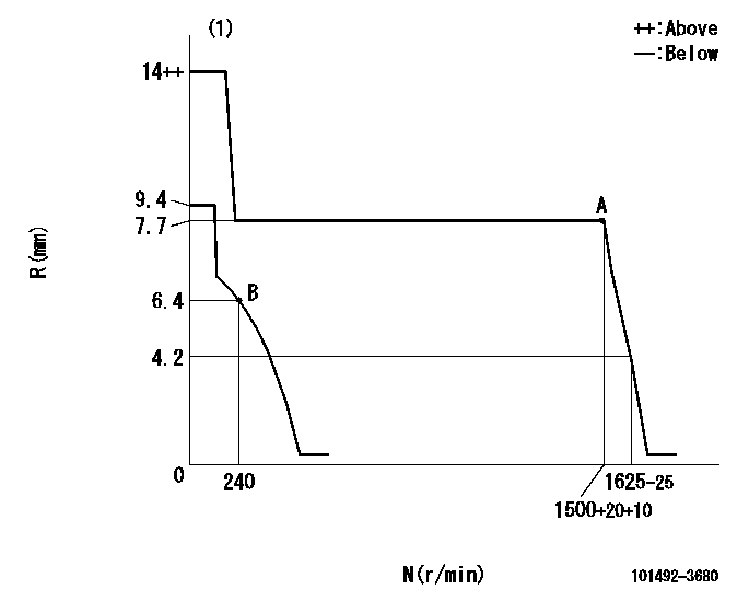
N:Pump speed
R:Rack position (mm)
(1)Target notch: K
----------
K=9
----------
----------
K=9
----------
Speed control lever angle

F:Full speed
I:Idle
(1)Stopper bolt setting
----------
----------
a=(43deg)+-5deg b=(26deg)+-5deg
----------
----------
a=(43deg)+-5deg b=(26deg)+-5deg
Stop lever angle

N:Pump normal
S:Stop the pump.
----------
----------
a=26.5deg+-5deg b=53deg+-5deg
----------
----------
a=26.5deg+-5deg b=53deg+-5deg
Timing setting

(1)Pump vertical direction
(2)Position of key groove at No 1 cylinder's beginning of injection
(3)Stamp aligning marks on the pump housing flange.
(4)-
(5)-
----------
----------
a=58deg+-3deg b=2deg+-30min
----------
----------
a=58deg+-3deg b=2deg+-30min
Information:
start by:a) remove fuel injection pump housing and governor 1. Install the fuel injection pump housing on tool (A).2. Remove the bolts (1) that hold the governor housing (2) to the fuel injection pump housing.3. Remove the governor housing (2). 4. Remove two springs (4) and the seat (5) from the governor housing.5. Remove the seat (7) from the shaft.6. Remove the spring (6) from the shaft.7. Remove the cover (3) from the pump housing. 8. Remove the shaft (8) and the lever (9) from the pump housing. 9. Remove the thrust collar (11) from the shaft.10. Remove the cover (10) from the pump housing. 11. Loosen the two bolts (13) that hold the torque spring assembly (12) and remove it from the pump housing. 12. Remove the pin (15) from the pump housing.13. Remove the screw (14) and the nut (16) from the pump housing.14. Remove the ring that holds the lever and remove the lever (18) from the dowel (17).15. Remove the dowel (17) from the pump housing. Dowel does not need to be removed unless camshaft is to be removed.
Pull on the shield only a small amount in each location so it will not have distortion or damage. A damaged shield must be replaced.
16. Remove the shield (19) from the camshaft with tool (B). 17. Install the timing pin (C) to hold the camshaft.18. Remove the bolts (20) that hold the flyweight assembly to the camshaft. 19. Remove the flyweight assembly (21) from the camshaft.20. Remove the timing pin (C) from the pump housing.Connection Of Governor To Fuel Injection Pump Housing
1. Put the fuel injection pump housing on the bracket assembly (A).2. Install the timing pin (B) to hold the camshaft.3. Put the flyweight assembly (1) in position on the camshaft. Be sure the pin that holds the shaft (2) is in position on the back of the flyweight assembly.4. Install the bolts that hold the flyweight assembly to the camshaft and tighten to a torque of 10 2 lb. ft. (1.38 0.28 mkg).5. Remove the timing pin (B). 6. Put the shield (3) in position over the flyweights. 7. Use the driver (C) to install the shield the remainder of the way on to the camshaft. 8. Put a new O-ring seal on the dowel (4) and install the dowel in the pump housing. Make the dowel even with the machined surface of the counterbore on the outside of the housing. 9. Put the lever (8) on the dowel (4) and install the ring that holds it on the dowel.10. Install the screw (6) and the nut (7) in the pump housing.11. Install the pin (5) in the pump housing. 12. Put the torque spring assembly (10) in position on the housing and tighten the two bolts (11) that hold it to the housing.13. Install the cover (9) on the pump housing. 14. Put the thrust collar (13) in position between the flyweights. Lift the flyweights up with a piece of wire
Have questions with 101492-3680?
Group cross 101492-3680 ZEXEL
Komatsu
101492-3680
INJECTION-PUMP ASSEMBLY
S4D95L
S4D95L