Information injection-pump assembly
ZEXEL
101492-3670
1014923670
KOMATSU
6204711460
6204711460

Rating:
Cross reference number
ZEXEL
101492-3670
1014923670
KOMATSU
6204711460
6204711460
Zexel num
Bosch num
Firm num
Name
Calibration Data:
Adjustment conditions
Test oil
1404 Test oil ISO4113 or {SAEJ967d}
1404 Test oil ISO4113 or {SAEJ967d}
Test oil temperature
degC
40
40
45
Nozzle and nozzle holder
105780-8140
Bosch type code
EF8511/9A
Nozzle
105780-0000
Bosch type code
DN12SD12T
Nozzle holder
105780-2080
Bosch type code
EF8511/9
Opening pressure
MPa
17.2
Opening pressure
kgf/cm2
175
Injection pipe
Outer diameter - inner diameter - length (mm) mm 6-2-600
Outer diameter - inner diameter - length (mm) mm 6-2-600
Tester oil delivery pressure
kPa
157
157
157
Tester oil delivery pressure
kgf/cm2
1.6
1.6
1.6
Direction of rotation (viewed from drive side)
Right R
Right R
Injection timing adjustment
Direction of rotation (viewed from drive side)
Right R
Right R
Injection order
1-2-4-3
Pre-stroke
mm
3.6
3.55
3.65
Rack position
Point A R=A
Point A R=A
Beginning of injection position
Drive side NO.1
Drive side NO.1
Difference between angles 1
Cyl.1-2 deg. 90 89.5 90.5
Cyl.1-2 deg. 90 89.5 90.5
Difference between angles 2
Cal 1-4 deg. 180 179.5 180.5
Cal 1-4 deg. 180 179.5 180.5
Difference between angles 3
Cal 1-3 deg. 270 269.5 270.5
Cal 1-3 deg. 270 269.5 270.5
Injection quantity adjustment
Adjusting point
A
Rack position
8.9
Pump speed
r/min
1400
1400
1400
Average injection quantity
mm3/st.
29.4
28.4
30.4
Max. variation between cylinders
%
0
-2.5
2.5
Basic
*
Fixing the lever
*
Injection quantity adjustment_02
Adjusting point
-
Rack position
10+-0.5
Pump speed
r/min
400
400
400
Average injection quantity
mm3/st.
10.5
9.5
11.5
Max. variation between cylinders
%
0
-15
15
Fixing the rack
*
Remarks
Adjust only variation between cylinders; adjust governor according to governor specifications.
Adjust only variation between cylinders; adjust governor according to governor specifications.
Test data Ex:
Governor adjustment
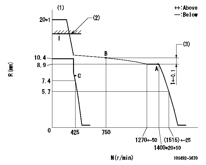
N:Pump speed
R:Rack position (mm)
(1)Notch fixed: K
(2)RACK CAP: R1
(3)Rack difference between N = N1 and N = N2
----------
K=20 R1=(17.5)mm N1=1400r/min N2=750r/min
----------
----------
K=20 R1=(17.5)mm N1=1400r/min N2=750r/min
----------
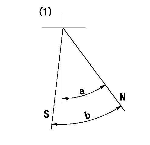
Speed control lever angle
F:Full speed
I:Idle
(1)Stopper bolt setting
----------
----------
a=(24deg)+-5deg b=(25deg)+-5deg
----------
----------
a=(24deg)+-5deg b=(25deg)+-5deg
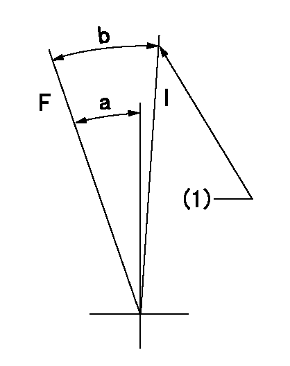
Stop lever angle
N:Pump normal
S:Stop the pump.
(1)No return spring
----------
----------
a=47deg+-5deg b=53deg+-5deg
----------
----------
a=47deg+-5deg b=53deg+-5deg
Timing setting

(1)Pump vertical direction
(2)Position of key groove at No 1 cylinder's beginning of injection
(3)Stamp aligning marks on the pump housing flange.
(4)-
(5)-
----------
----------
a=59deg36min+-3deg b=0deg24min+-30min
----------
----------
a=59deg36min+-3deg b=0deg24min+-30min
Information:
start by: a) remove fuel injection pump housing and governor 1. Install the fuel injection pump housing on tool (A). 2. Remove the bolt (1) from the cover. Turn the injection pump camshaft until the timing pin (B) can be installed in the camshaft.3. Install tool (C) in the threads of the sleeve (3). Tighten the bolt until the sleeve can be removed.4. Remove the four bolts (4) that hold the body to the housing.5. Remove the body (2) from the housing. 6. Remove the idler gear (5) from the body.7. Remove the O-ring seal (6) from the body. Remove the two lip type seals (7) from the body. 8. Remove the drive gear (9) from the shaft.9. Remove the key (8) from the shaft.Install Fuel Transfer Pump
1. Install the key (1) and the drive gear (2) on the shaft.2. Put 5S1454 Sealing Compound on the outside diameter of the seals. 3. Install the inner seal in the body with the lip of the seal toward the inside with tooling (A).4. Install the outer seal in the body with the lip of the seal toward the outside with tooling (B).5. Remove the extra sealing compound from the body and the seals after installation. 6. Install the O-ring seal (4) and the idler gear (3) in the body. 7. Install the body (5) on the housing. 8. Install the four bolts (7) that hold the body to the housing.9. Put the timing pin (D) in position to keep the camshaft from turning.10. Put the sleeve (6) on the camshaft. 11. Tighten the sleeve into position on the shaft with 4B4280 Washer of tooling (C) approximately .25 in. (6.4 mm). Tighten the sleeve the remainder of the way with the 4N3371 Washer. The 4N3371 Washer is the washer which is on the tachometer drive bolt.
Do not hit the sleeve to install. Damage to governor will result.
12. The end play of the camshaft must be .023 .018 in. (0.58 0.46 mm) after sleeve (6) is installed.end by: a) install fuel injection pump housing and governor