Information injection-pump assembly
ZEXEL
101492-3630
1014923630
KOMATSU
6204711270
6204711270

Rating:
Cross reference number
ZEXEL
101492-3630
1014923630
KOMATSU
6204711270
6204711270
Zexel num
Bosch num
Firm num
Name
Calibration Data:
Adjustment conditions
Test oil
1404 Test oil ISO4113 or {SAEJ967d}
1404 Test oil ISO4113 or {SAEJ967d}
Test oil temperature
degC
40
40
45
Nozzle and nozzle holder
105780-8140
Bosch type code
EF8511/9A
Nozzle
105780-0000
Bosch type code
DN12SD12T
Nozzle holder
105780-2080
Bosch type code
EF8511/9
Opening pressure
MPa
17.2
Opening pressure
kgf/cm2
175
Injection pipe
Outer diameter - inner diameter - length (mm) mm 6-2-600
Outer diameter - inner diameter - length (mm) mm 6-2-600
Overflow valve
132424-0620
Overflow valve opening pressure
kPa
157
123
191
Overflow valve opening pressure
kgf/cm2
1.6
1.25
1.95
Tester oil delivery pressure
kPa
157
157
157
Tester oil delivery pressure
kgf/cm2
1.6
1.6
1.6
Direction of rotation (viewed from drive side)
Right R
Right R
Injection timing adjustment
Direction of rotation (viewed from drive side)
Right R
Right R
Injection order
1-2-4-3
Pre-stroke
mm
3.6
3.55
3.65
Rack position
Point A R=A
Point A R=A
Beginning of injection position
Drive side NO.1
Drive side NO.1
Difference between angles 1
Cyl.1-2 deg. 90 89.5 90.5
Cyl.1-2 deg. 90 89.5 90.5
Difference between angles 2
Cal 1-4 deg. 180 179.5 180.5
Cal 1-4 deg. 180 179.5 180.5
Difference between angles 3
Cal 1-3 deg. 270 269.5 270.5
Cal 1-3 deg. 270 269.5 270.5
Injection quantity adjustment
Adjusting point
A
Rack position
9.7
Pump speed
r/min
1225
1225
1225
Average injection quantity
mm3/st.
34.3
33.3
35.3
Max. variation between cylinders
%
0
-2.5
2.5
Basic
*
Fixing the lever
*
Injection quantity adjustment_02
Adjusting point
-
Rack position
10.2+-0.
5
Pump speed
r/min
410
410
410
Average injection quantity
mm3/st.
10.5
9.5
11.5
Max. variation between cylinders
%
0
-15
15
Fixing the rack
*
Remarks
Adjust only variation between cylinders; adjust governor according to governor specifications.
Adjust only variation between cylinders; adjust governor according to governor specifications.
Test data Ex:
Governor adjustment
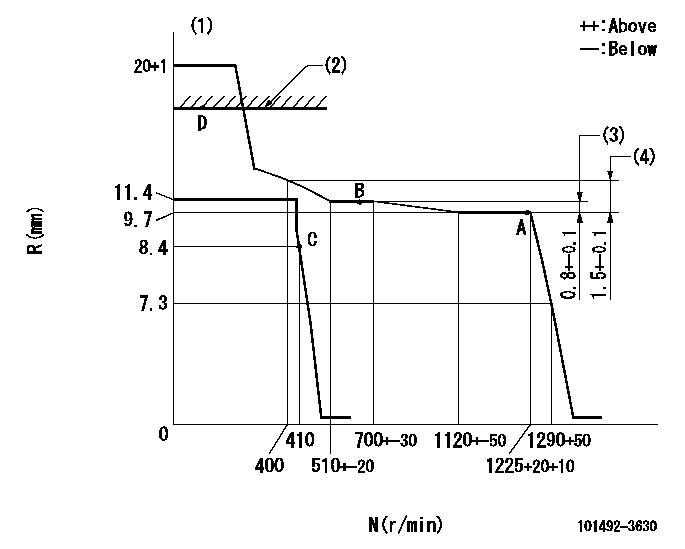
N:Pump speed
R:Rack position (mm)
(1)Target notch: K
(2)RACK CAP: R1
(3)Rack difference between N = N1 and N = N2
(4)Rack difference between N = N3 and N = N4
----------
K=20 R1=(17.5)mm N1=1225r/min N2=650r/min N3=1225r/min N4=400r/min
----------
----------
K=20 R1=(17.5)mm N1=1225r/min N2=650r/min N3=1225r/min N4=400r/min
----------
Speed control lever angle
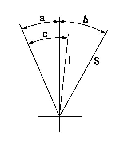
I:Idle
S:Stop
----------
----------
a=26deg+-5deg b=32deg+-3deg c=27deg+-5deg
----------
----------
a=26deg+-5deg b=32deg+-3deg c=27deg+-5deg
Timing setting

(1)Pump vertical direction
(2)Position of key groove at No 1 cylinder's beginning of injection
(3)Stamp aligning marks on the pump housing flange.
(4)-
(5)-
----------
----------
a=59deg36min+-3deg b=0deg24min+-30min
----------
----------
a=59deg36min+-3deg b=0deg24min+-30min
Information:
Start By:a. remove oil pump 1. Check each main bearing cap (2) for its location on the engine. Each cap has an arrow (1) which shows the direction of the front of the block and a number (3) which gives the location of that cap.2. Remove No. 2 through No. 6 main bearing caps from the engine. Remove the lower bearings from the caps.3. Remove the thrust plate from each side of the No. 4 upper main bearing. 4. Turn the crankshaft until Tool (A) can be installed in oil hole (4). Turn the crankshaft in the direction which will push the upper main bearing out, tab end first.
If the crankshaft is turned in the wrong direction, the tab of the bearing will be pushed between the crankshaft and the cylinder block. This will cause damage to the crankshaft and block.
Install the main bearings dry when clearance checks are made. Put clean engine oil on the main bearings for final assembly. 5. Install lower bearings in the bearing caps.6. Install upper bearings in the cylinder block with Tool (A). Be sure tab (5) on the back of the bearings fits in the groove of the caps and cylinder block. When the bearing clearance is checked and the engine is in a vertical position such as in the vehicle, the crankshaft will have to be lifted up and held against the upper halves of the main bearings to get a correct measurement with plastigage (B). The Plastigage will not hold the weight of the crankshaft and give a correct indication. If the engine is in a horizontal position, such as on an engine stand, it is not necessary to hold the crankshaft up. Do not turn crankshaft when the Plastigage is in position to check clearance.
Do not use an impact wrench to tighten the bolts the additional 120 degrees.
7. Check the bearing clearance with Plastigage (B) as follows:a. Put clean oil on the threads of the cap bolts. Install the caps and cap bolts, finger tight.b. Tighten the bolts on the tab end of the caps first to a torque of 260 14 N m (190 10 lb ft)c. Tighten the bolts on the other end of the caps to a torque of 260 14 N m (190 10 lb ft).d. Put a mark across the bolt head and cap. Tighten the bolts opposite the tab end 120 degrees more. Tighten the bolts on the tab end of the cap 120 degrees more. Make sure the main bearing caps are installed with their identification number (7) in alignment with the identification number on the left side of the cylinder block and arrow (6) toward the front of the block.8. Remove the main bearing caps and Tool (B).9. Measure the thickness of the Plastigage to find the bearing clearance. The clearance for new bearings must be 0.091 to 0.186 mm (.0036 to .0073 in). The maximum clearance for used bearings is 0.025 mm (0.010 in).10.