Information injection-pump assembly
ZEXEL
101492-3610
1014923610
KOMATSU
6204711730
6204711730

Rating:
Cross reference number
ZEXEL
101492-3610
1014923610
KOMATSU
6204711730
6204711730
Zexel num
Bosch num
Firm num
Name
Calibration Data:
Adjustment conditions
Test oil
1404 Test oil ISO4113 or {SAEJ967d}
1404 Test oil ISO4113 or {SAEJ967d}
Test oil temperature
degC
40
40
45
Nozzle and nozzle holder
105780-8140
Bosch type code
EF8511/9A
Nozzle
105780-0000
Bosch type code
DN12SD12T
Nozzle holder
105780-2080
Bosch type code
EF8511/9
Opening pressure
MPa
17.2
Opening pressure
kgf/cm2
175
Injection pipe
Outer diameter - inner diameter - length (mm) mm 6-2-600
Outer diameter - inner diameter - length (mm) mm 6-2-600
Tester oil delivery pressure
kPa
157
157
157
Tester oil delivery pressure
kgf/cm2
1.6
1.6
1.6
Direction of rotation (viewed from drive side)
Right R
Right R
Injection timing adjustment
Direction of rotation (viewed from drive side)
Right R
Right R
Injection order
1-2-4-3
Pre-stroke
mm
3.6
3.55
3.65
Rack position
Point A R=A
Point A R=A
Beginning of injection position
Drive side NO.1
Drive side NO.1
Difference between angles 1
Cyl.1-2 deg. 90 89.5 90.5
Cyl.1-2 deg. 90 89.5 90.5
Difference between angles 2
Cal 1-4 deg. 180 179.5 180.5
Cal 1-4 deg. 180 179.5 180.5
Difference between angles 3
Cal 1-3 deg. 270 269.5 270.5
Cal 1-3 deg. 270 269.5 270.5
Injection quantity adjustment
Adjusting point
A
Rack position
10.5
Pump speed
r/min
1400
1400
1400
Average injection quantity
mm3/st.
36.5
35.5
37.5
Max. variation between cylinders
%
0
-2.5
2.5
Basic
*
Fixing the lever
*
Injection quantity adjustment_02
Adjusting point
-
Rack position
10.5+-0.
5
Pump speed
r/min
400
400
400
Average injection quantity
mm3/st.
10.5
9.5
11.5
Max. variation between cylinders
%
0
-15
15
Fixing the rack
*
Remarks
Adjust only variation between cylinders; adjust governor according to governor specifications.
Adjust only variation between cylinders; adjust governor according to governor specifications.
Test data Ex:
Governor adjustment
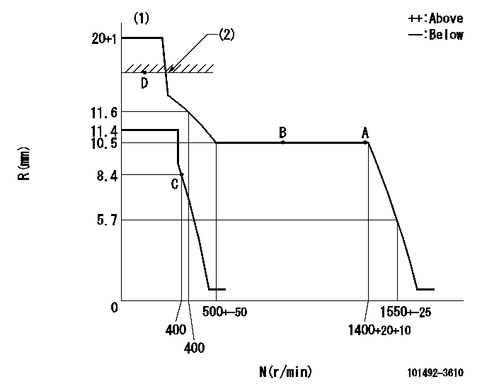
N:Pump speed
R:Rack position (mm)
(1)Target notch: K
(2)RACK CAP: R1
----------
K=17 R1=(17.5)mm
----------
----------
K=17 R1=(17.5)mm
----------
Speed control lever angle
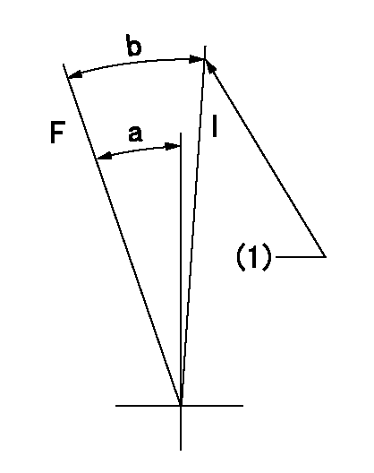
F:Full speed
I:Idle
(1)Stopper bolt setting
----------
----------
a=22deg+-5deg b=25deg+-5deg
----------
----------
a=22deg+-5deg b=25deg+-5deg
Stop lever angle
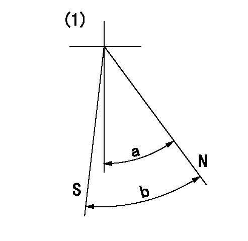
N:Pump normal
S:Stop the pump.
(1)No return spring
----------
----------
a=47deg+-5deg b=53deg+-5deg
----------
----------
a=47deg+-5deg b=53deg+-5deg
Timing setting

(1)Pump vertical direction
(2)Position of key groove at No 1 cylinder's beginning of injection
(3)Stamp aligning marks on the pump housing flange.
(4)-
----------
----------
a=59deg36min+-3deg b=0deg24min+-30min
----------
----------
a=59deg36min+-3deg b=0deg24min+-30min
Information:
3. Remove bearing caps (1) from the two connecting rods. Put pieces of rubber hose or tape on the threads of the connecting rod bolts as protection for the crankshaft. 4. Push the pistons up until the piston rings are clear of the cylinder liner. Remove pistons (2). Keep each cap with the respective connecting rod.
Do not turn the crankshaft while any of the connecting rods are in the engine without the caps installed. Do not damage the cooling tubes when the pistons are removed.
Install Pistons
1. Put clean engine oil on the piston rings, connecting rod bearings and cylinder liners. 2. Put two pistons in position opposite of each other in the correct bore of the block. install pistons (1) with Tool (A).
Be sure the pistons are installed with flat surfaces (2) of the connecting rods toward each other and the chamfered sides (4) toward the crankshaft.
For more detail about installation of connecting rod bearings, see remove and install connecting rod bearings.3. Check the bearing clearance with Plastigage (B).
Do not use an impact wrench to tighten the nuts the additional 120 degrees.
4. Put clean engine oil on bolts (5). Install caps (3) and nuts finger tight. Tighten each nut to a torque of 80 8 N m (60 6 lb ft). Put a mark across the nuts and bolts. Tighten each nut 120 degrees more.5. Check the side clearance between two connecting rods on the same crankshaft journal. Clearance must be 0.28 to 0.84 mm (.011 to .033 in) for new rods.End By:a. install oil pumpb. install cylinder headsDisassemble & Assemble Pistons
Start By:a. remove pistons 1. Remove bearing halves (2) from the connecting rod and connecting rod cap. New retainer rings allow the use of pliers to remove retainer rings (1).2. Use Tool (C) or pliers to remove retainer rings (1) from each side of the piston. Remove pin (3) and the connecting rod from the piston. 3. Use Tool (A) to remove the piston rings from piston (4). 4. Heat the connecting rod to a temperature of 177° - 204°C (350° - 400°F). Put 5P-8651 Spacer (12) in the base plate. Put connecting rod in position on the base plate of Tooling (B).5. Put the connecting rod piston pin bearing end in the center of the port assembly of Tooling (B). Install pin (8) in the center of the bore for the connecting rod bearings.6. Install 5P-8650 adapter (10). Put the hole in the adapter in alignment with the hole in the base plate of Tooling (B).7. Install clamp bar (11) and clamp pin (7).8. Install new piston pin bearing (6) on adapter (10). The old bearing is pushed out by Tooling (B) as the new bearing is installed.9. Put 5P8649 Adapter (9) in position as shown with the taper side down. The piston pin bearing joint must be in alignment with the hole in adapter (10) and the base plate of Tooling (B).10. Put pusher (5) on adapter (9).11. Use Tooling (B) to push