Information injection-pump assembly
ZEXEL
101492-3600
1014923600

Rating:
Cross reference number
ZEXEL
101492-3600
1014923600
Zexel num
Bosch num
Firm num
Name
Calibration Data:
Adjustment conditions
Test oil
1404 Test oil ISO4113 or {SAEJ967d}
1404 Test oil ISO4113 or {SAEJ967d}
Test oil temperature
degC
40
40
45
Nozzle and nozzle holder
105780-8140
Bosch type code
EF8511/9A
Nozzle
105780-0000
Bosch type code
DN12SD12T
Nozzle holder
105780-2080
Bosch type code
EF8511/9
Opening pressure
MPa
17.2
Opening pressure
kgf/cm2
175
Injection pipe
Outer diameter - inner diameter - length (mm) mm 6-2-600
Outer diameter - inner diameter - length (mm) mm 6-2-600
Tester oil delivery pressure
kPa
157
157
157
Tester oil delivery pressure
kgf/cm2
1.6
1.6
1.6
Direction of rotation (viewed from drive side)
Right R
Right R
Injection timing adjustment
Direction of rotation (viewed from drive side)
Right R
Right R
Injection order
1-2-4-3
Pre-stroke
mm
3.6
3.55
3.65
Rack position
Point A R=A
Point A R=A
Beginning of injection position
Drive side NO.1
Drive side NO.1
Difference between angles 1
Cyl.1-2 deg. 90 89.5 90.5
Cyl.1-2 deg. 90 89.5 90.5
Difference between angles 2
Cal 1-4 deg. 180 179.5 180.5
Cal 1-4 deg. 180 179.5 180.5
Difference between angles 3
Cal 1-3 deg. 270 269.5 270.5
Cal 1-3 deg. 270 269.5 270.5
Injection quantity adjustment
Adjusting point
A
Rack position
10.5
Pump speed
r/min
1400
1400
1400
Average injection quantity
mm3/st.
36.3
35.3
37.3
Max. variation between cylinders
%
0
-2.5
2.5
Basic
*
Fixing the lever
*
Injection quantity adjustment_02
Adjusting point
-
Rack position
10.7+-0.
5
Pump speed
r/min
375
375
375
Average injection quantity
mm3/st.
10.5
9.5
11.5
Max. variation between cylinders
%
0
-15
15
Fixing the rack
*
Remarks
Adjust only variation between cylinders; adjust governor according to governor specifications.
Adjust only variation between cylinders; adjust governor according to governor specifications.
Test data Ex:
Governor adjustment
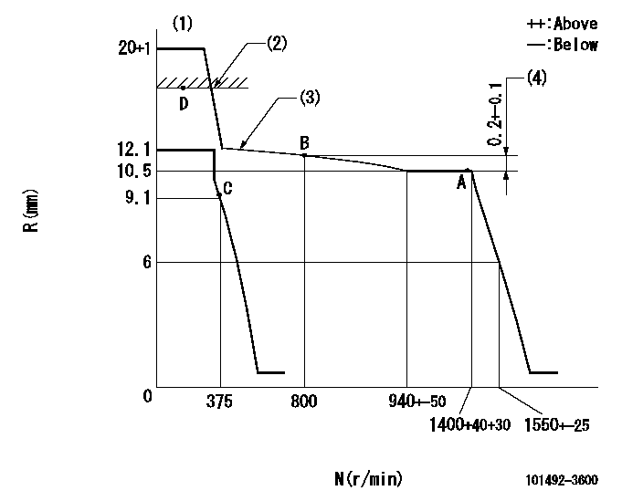
N:Pump speed
R:Rack position (mm)
(1)Target notch: K
(2)RACK CAP: R1
(3)The torque control spring must does not have a set force.
(4)Rack difference between N = N1 and N = N2
----------
K=16 R1=(17.5)mm N1=1400r/min N2=800r/min
----------
----------
K=16 R1=(17.5)mm N1=1400r/min N2=800r/min
----------
Speed control lever angle

F:Full speed
I:Idle
(1)Stopper bolt setting
----------
----------
a=18deg+-5deg b=26deg+-5deg
----------
----------
a=18deg+-5deg b=26deg+-5deg
Stop lever angle

N:Pump normal
S:Stop the pump.
----------
----------
a=26.5deg+-5deg b=53deg+-5deg
----------
----------
a=26.5deg+-5deg b=53deg+-5deg
Timing setting

(1)Pump vertical direction
(2)Position of key groove at No 1 cylinder's beginning of injection
(3)Stamp aligning marks on the pump housing flange.
(4)-
----------
----------
a=59deg36min+-3deg b=0deg24min+-30min
----------
----------
a=59deg36min+-3deg b=0deg24min+-30min
Information:
Start By:a. remove valve cover 1. Disconnect fuel line nut (1). Remove nut (2) and O-ring seal. Disconnect fuel line nut (4) and remove fuel line assembly (3).
Put protection caps on all fuel line openings.
2. Remove retainer (5) from fuel adapter with Tool (B). 3. Install Tooling (C) and remove fuel nozzle assembly from adapter. 4. Install Tool (D) and remove adapter (6). 5. Remove carbon seal stop (7) with Tool (E). 6. Remove washer (8) and bleed screw (9) from fuel nozzle assembly (10). The following steps are for the installation of the fuel injection nozzles and adapters. 7. Install new carbon seal stop (7) with Tool (E). 8. Make sure the correct washer (8) is used when the nozzle assembly (10) is installed. Always use a new washer anytime the bleed screw (9) is loosened or removed. Install fuel nozzle assembly (10) in adapter (6). Install retainer (5) to a torque of 48 7 N m (35 5 lb ft). 9. Put 5P-3931 Anti-Seize Compound on the threads of the adapter before installation. Install fuel adapter (6) with Tool (D). Torque for the adapter is 200 14 N m (150 10 lb ft).10. Install fuel injection line assembly (3) (finger tighten connections first). Install the O-ring seal and nut (2) to a torque of 30 7 N m (22 5 lb ft). Reconnect fuel line nut (1) to a torque of 40 7 N m (30 5 lb ft). Use Tool (A) to reconnect fuel line nut (4) to a torque of 40 7 N m (30 5 lb ft).End By:a. install valve cover