Information injection-pump assembly
BOSCH
9 400 614 435
9400614435
ZEXEL
101492-3400
1014923400
KOMATSU
6144731111
6144731111
Rating:
Service parts 101492-3400 INJECTION-PUMP ASSEMBLY:
1.
_
5.
AUTOM. ADVANCE MECHANIS
6.
COUPLING PLATE
7.
COUPLING PLATE
8.
_
9.
_
11.
Nozzle and Holder
6144-13-3100
12.
Open Pre:MPa(Kqf/cm2)
18.6{190}
15.
NOZZLE SET
Cross reference number
BOSCH
9 400 614 435
9400614435
ZEXEL
101492-3400
1014923400
KOMATSU
6144731111
6144731111
Zexel num
Bosch num
Firm num
Name
101492-3400
9 400 614 435
6144731111 KOMATSU
INJECTION-PUMP ASSEMBLY
4D94 * K
4D94 * K
Calibration Data:
Adjustment conditions
Test oil
1404 Test oil ISO4113 or {SAEJ967d}
1404 Test oil ISO4113 or {SAEJ967d}
Test oil temperature
degC
40
40
45
Nozzle and nozzle holder
105780-8140
Bosch type code
EF8511/9A
Nozzle
105780-0000
Bosch type code
DN12SD12T
Nozzle holder
105780-2080
Bosch type code
EF8511/9
Opening pressure
MPa
17.2
Opening pressure
kgf/cm2
175
Injection pipe
Outer diameter - inner diameter - length (mm) mm 6-2-600
Outer diameter - inner diameter - length (mm) mm 6-2-600
Tester oil delivery pressure
kPa
157
157
157
Tester oil delivery pressure
kgf/cm2
1.6
1.6
1.6
Direction of rotation (viewed from drive side)
Right R
Right R
Injection timing adjustment
Direction of rotation (viewed from drive side)
Right R
Right R
Injection order
1-2-4-3
Pre-stroke
mm
3.2
3.15
3.25
Rack position
Point A R=A
Point A R=A
Beginning of injection position
Drive side NO.1
Drive side NO.1
Difference between angles 1
Cyl.1-2 deg. 90 89.5 90.5
Cyl.1-2 deg. 90 89.5 90.5
Difference between angles 2
Cal 1-4 deg. 180 179.5 180.5
Cal 1-4 deg. 180 179.5 180.5
Difference between angles 3
Cal 1-3 deg. 270 269.5 270.5
Cal 1-3 deg. 270 269.5 270.5
Injection quantity adjustment
Adjusting point
A
Rack position
8.7
Pump speed
r/min
1200
1200
1200
Average injection quantity
mm3/st.
31.5
30.5
32.5
Max. variation between cylinders
%
0
-2
2
Basic
*
Fixing the lever
*
Injection quantity adjustment_02
Adjusting point
B
Rack position
-
Pump speed
r/min
400
400
400
Average injection quantity
mm3/st.
9
8
10
Max. variation between cylinders
%
0
-15
15
Fixing the rack
*
Remarks
Adjust only variation between cylinders; adjust governor according to governor specifications.
Adjust only variation between cylinders; adjust governor according to governor specifications.
Test data Ex:
Governor adjustment
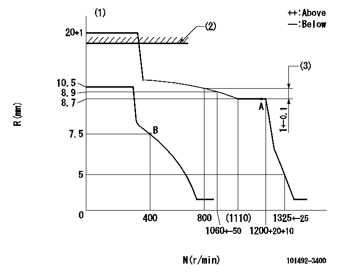
N:Pump speed
R:Rack position (mm)
(1)Target notch: K
(2)RACK CAP: R1
(3)Rack difference between N = N1 and N = N2
----------
K=14 R1=18+1mm N1=800r/min N2=1200r/min
----------
----------
K=14 R1=18+1mm N1=800r/min N2=1200r/min
----------
Speed control lever angle

F:Full speed
I:Idle
S:Stop
----------
----------
a=17deg+-5deg b=32deg+-3deg c=25deg+-5deg
----------
----------
a=17deg+-5deg b=32deg+-3deg c=25deg+-5deg
Timing setting

(1)Pump vertical direction
(2)Position of key groove at No 1 cylinder's beginning of injection
(3)Stamp aligning marks on the pump housing flange.
(4)-
(5)-
----------
----------
a=58deg+-3deg b=2deg+-30min
----------
----------
a=58deg+-3deg b=2deg+-30min
Information:
Start By:a. remove exhaust manifoldsb. remove push rods and valve liftersc. remove water temperature regulators Put protection caps on all fuel openings. 1. Remove the bolts and valve cover base (1) from the cylinder head assembly.2. Disconnect hose (2) from the cylinder head assembly. 3. Put identification marks on wires (3), and disconnect them from the sending unit. 4. Remove six head bolts (4), and install Tooling (A). 5. Fasten a hoist to Tooling (A), and remove the remainder of the bolts that fasten the head assembly.6. Remove cylinder head assembly (5). The weight of the head assembly is 102 kg (224 lb). A new spacer plate gasket must be installed when the cylinder head is removed. See Remove & Install Spacer Plate.Install Cylinder Head Assemblies
1. Thoroughly clean the spacer plates and bottom surface of the cylinder head assemblies. Install a new head gasket and seals. Do not use any adhesives. A new spacer plate gasket must be installed when the cylinder head assembly is removed. See Remove And Install Spacer Plate. 2. Fasten Tooling (A) to the cylinder head assembly, and put cylinder head assembly (1) into position on the spacer plate. The use of guide bolts will help put the cylinder head assembly in alignment with the spacer plate.
(1) Large bolts (3/4 in). Put 6V-4876 Molycoat Paste Lubricant on the threads and between washer and underside of the cylinder head bolts. (2) Small bolts (3/8 in). See Step 3h.3. Install cylinder head bolts and washers. Tighten the bolts in the following sequence:a. Tighten bolts 1 through 10 in number sequence to 270 25 N m (200 20 lb ft)b. Tighten bolts 1 through 10 in number sequence to 470 20 N m (345 15 lb ft)c. Tighten bolts 1 through 10 in number sequence again to 470 20 N m (345 15 lb ft).d. Install the rocker arm shafts for the engine valves.e. Tighten bolts 11 through 18 in number sequence to 270 25 N m (200 20 lb ft).f. Tighten bolts 11 through 18 in number sequence to 450 20 N m (330 15 lb ft).g. Tighten bolts 11 through 18 in number sequence again to 450 20 N m (330 15 lb ft).h. Tighten the nine small bolts (2) to 45 7 N m (33 5 lb ft). 4. Connect hose (3) and the wire assembly to the cylinder head. 5. Install valve cover base (2) to the cylinder head. Tighten the bolts to a torque of 14 4 N m (10 3 lb ft) and the sequence as shown.End By:a. install water temperature regulatorsb. install push rods and valve liftersc. install exhaust manifolds
Have questions with 101492-3400?
Group cross 101492-3400 ZEXEL
Komatsu
101492-3400
9 400 614 435
6144731111
INJECTION-PUMP ASSEMBLY
4D94
4D94