Information injection-pump assembly
BOSCH
9 400 614 434
9400614434
ZEXEL
101492-3340
1014923340
KOMATSU
6130721151
6130721151
Rating:
Service parts 101492-3340 INJECTION-PUMP ASSEMBLY:
1.
_
5.
AUTOM. ADVANCE MECHANIS
6.
COUPLING PLATE
8.
_
9.
_
10.
NOZZLE AND HOLDER ASSY
11.
Nozzle and Holder
12.
Open Pre:MPa(Kqf/cm2)
13.
NOZZLE-HOLDER
14.
NOZZLE
15.
NOZZLE SET
Cross reference number
BOSCH
9 400 614 434
9400614434
ZEXEL
101492-3340
1014923340
KOMATSU
6130721151
6130721151
Zexel num
Bosch num
Firm num
Name
101492-3340
9 400 614 434
6130721151 KOMATSU
INJECTION-PUMP ASSEMBLY
4D105 K 14BC INJECTION PUMP ASSY PE4A,5A, PE
4D105 K 14BC INJECTION PUMP ASSY PE4A,5A, PE
Calibration Data:
Adjustment conditions
Test oil
1404 Test oil ISO4113 or {SAEJ967d}
1404 Test oil ISO4113 or {SAEJ967d}
Test oil temperature
degC
40
40
45
Nozzle and nozzle holder
105780-8140
Bosch type code
EF8511/9A
Nozzle
105780-0000
Bosch type code
DN12SD12T
Nozzle holder
105780-2080
Bosch type code
EF8511/9
Opening pressure
MPa
17.2
Opening pressure
kgf/cm2
175
Injection pipe
Outer diameter - inner diameter - length (mm) mm 6-2-600
Outer diameter - inner diameter - length (mm) mm 6-2-600
Tester oil delivery pressure
kPa
157
157
157
Tester oil delivery pressure
kgf/cm2
1.6
1.6
1.6
Direction of rotation (viewed from drive side)
Right R
Right R
Injection timing adjustment
Direction of rotation (viewed from drive side)
Right R
Right R
Injection order
1-2-4-3
Pre-stroke
mm
3
2.95
3.05
Beginning of injection position
Governor side NO.1
Governor side NO.1
Difference between angles 1
Cyl.1-2 deg. 90 89.5 90.5
Cyl.1-2 deg. 90 89.5 90.5
Difference between angles 2
Cal 1-4 deg. 180 179.5 180.5
Cal 1-4 deg. 180 179.5 180.5
Difference between angles 3
Cal 1-3 deg. 270 269.5 270.5
Cal 1-3 deg. 270 269.5 270.5
Injection quantity adjustment
Adjusting point
A
Rack position
8.3
Pump speed
r/min
1050
1050
1050
Average injection quantity
mm3/st.
41.3
40.3
42.3
Max. variation between cylinders
%
0
-2
2
Basic
*
Fixing the rack
*
Injection quantity adjustment_02
Adjusting point
B
Rack position
10.4
Pump speed
r/min
700
700
700
Average injection quantity
mm3/st.
55.9
54.9
56.9
Max. variation between cylinders
%
0
-4
4
Fixing the lever
*
Injection quantity adjustment_03
Adjusting point
C
Rack position
8.1+-0.5
Pump speed
r/min
375
375
375
Average injection quantity
mm3/st.
13.9
12.1
15.7
Max. variation between cylinders
%
0
-10
10
Fixing the rack
*
Test data Ex:
Governor adjustment
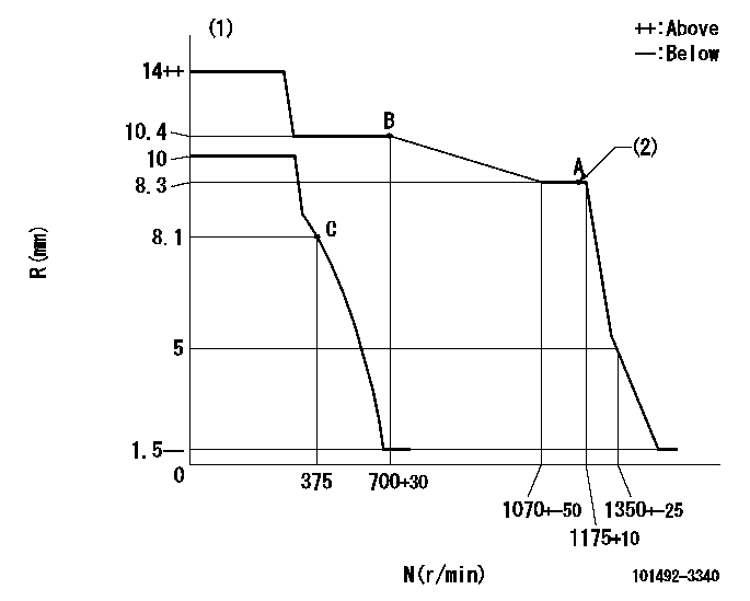
N:Pump speed
R:Rack position (mm)
(1)Target notch: K
(2)Supplied with torque spring not set.
----------
K=13
----------
----------
K=13
----------
Speed control lever angle

F:Full speed
I:Idle
S:Stop
----------
----------
a=12.5deg+-5deg b=32deg+-3deg c=21deg+-3deg
----------
----------
a=12.5deg+-5deg b=32deg+-3deg c=21deg+-3deg
Information:
1. Disconnect hose (1) at governor control cylinder (2).2. Remove pin (4).3. Remove governor control cylinder (2).4. Note the position of linkage (3) in the lever, and remove linkage (3). The following steps are for installation of the governor control cylinder.5. Adjust linkage (3) so the distance between rod end centers is 84.07 mm (3.309 in).6. Install linkage (3) in its original position in the lever.7. Be sure lever (5) on the governor shaft is at 15 degrees from vertical (CW when viewed from the left side of the machine) with engine at low idle.8. Install control cylinder (2). Install pin (4) through link (3) and lever (5).9. Connect hose (1) to governor control cylinder (2).10. Adjust linkage (3) so lever (5) is at low idle when governor control cylinder is fully retracted.Disassemble & Assemble Governor Control Cylinder
Start By:a. remove governor control cylinder 1. Remove cover (1).
A spring force of 44.5 N (10 lb) will be released when the bolt that holds piston (8) is removed. Hold the components of the governor control cylinder to prevent unexpected movement of components and personal injury.
2. Remove the bolt that holds piston (6), and remove the piston and springs.3. Remove O-ring seal (2) and sleeve (5).4. Remove seals (3) and (4) from piston (6). The following steps are for the assembly of the governor control cylinder.5. Install lip-type seal (3) and "T" seal on the piston (6). Install the lip-type seal with the lip facing the cylinder pressure source.6. Install shell (5) in the air chamber body.7. Put 5P-0960 Multipurpose Grease inside the shell.8. Carefully install piston (6) and springs into the air chamber body.9. Install the bolt to hold the piston.10. Install O-ring seal (2) and cover (1).End By:a. install governor control cylinder
Have questions with 101492-3340?
Group cross 101492-3340 ZEXEL
Komatsu
101492-3340
9 400 614 434
6130721151
INJECTION-PUMP ASSEMBLY
4D105
4D105