Information injection-pump assembly
BOSCH
9 400 610 364
9400610364
ZEXEL
101492-3320
1014923320
KOMATSU
6114711400
6114711400
Rating:
Service parts 101492-3320 INJECTION-PUMP ASSEMBLY:
1.
_
5.
AUTOM. ADVANCE MECHANIS
7.
COUPLING PLATE
8.
_
9.
_
11.
Nozzle and Holder
6114-11-3200
12.
Open Pre:MPa(Kqf/cm2)
13.7{140}
15.
NOZZLE SET
Cross reference number
BOSCH
9 400 610 364
9400610364
ZEXEL
101492-3320
1014923320
KOMATSU
6114711400
6114711400
Zexel num
Bosch num
Firm num
Name
101492-3320
9 400 610 364
6114711400 KOMATSU
INJECTION-PUMP ASSEMBLY
4D130 * K 14BC INJECTION PUMP ASSY PE4A,5A, PE
4D130 * K 14BC INJECTION PUMP ASSY PE4A,5A, PE
Calibration Data:
Adjustment conditions
Test oil
1404 Test oil ISO4113 or {SAEJ967d}
1404 Test oil ISO4113 or {SAEJ967d}
Test oil temperature
degC
40
40
45
Nozzle and nozzle holder
105780-8140
Bosch type code
EF8511/9A
Nozzle
105780-0000
Bosch type code
DN12SD12T
Nozzle holder
105780-2080
Bosch type code
EF8511/9
Opening pressure
MPa
17.2
Opening pressure
kgf/cm2
175
Injection pipe
Outer diameter - inner diameter - length (mm) mm 6-2-600
Outer diameter - inner diameter - length (mm) mm 6-2-600
Overflow valve
132424-0620
Overflow valve opening pressure
kPa
157
123
191
Overflow valve opening pressure
kgf/cm2
1.6
1.25
1.95
Tester oil delivery pressure
kPa
157
157
157
Tester oil delivery pressure
kgf/cm2
1.6
1.6
1.6
Direction of rotation (viewed from drive side)
Right R
Right R
Injection timing adjustment
Direction of rotation (viewed from drive side)
Right R
Right R
Injection order
1-2-4-3
Pre-stroke
mm
2.4
2.35
2.45
Rack position
R=10
Beginning of injection position
Drive side NO.1
Drive side NO.1
Difference between angles 1
Cyl.1-2 deg. 90 89.5 90.5
Cyl.1-2 deg. 90 89.5 90.5
Difference between angles 2
Cal 1-4 deg. 180 179.5 180.5
Cal 1-4 deg. 180 179.5 180.5
Difference between angles 3
Cal 1-3 deg. 270 269.5 270.5
Cal 1-3 deg. 270 269.5 270.5
Injection quantity adjustment
Adjusting point
A
Rack position
10.6
Pump speed
r/min
950
950
950
Average injection quantity
mm3/st.
122
121
123
Max. variation between cylinders
%
0
-2
2
Basic
*
Fixing the rack
*
Injection quantity adjustment_02
Adjusting point
D
Rack position
5.2
Pump speed
r/min
315
315
315
Average injection quantity
mm3/st.
24
21.6
26.4
Max. variation between cylinders
%
0
-10
10
Fixing the rack
*
Test data Ex:
Governor adjustment
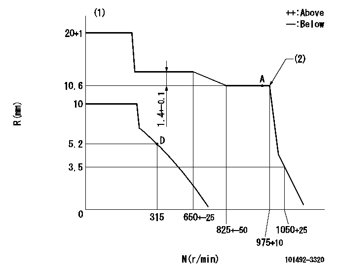
N:Pump speed
R:Rack position (mm)
(1)Target notch: K
(2)Supplied with torque spring not set.
----------
K=12
----------
----------
K=12
----------
Speed control lever angle
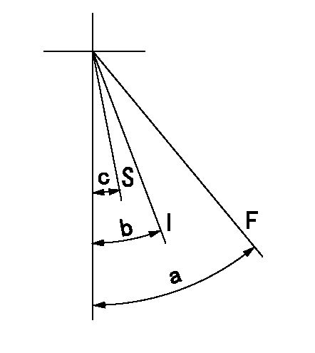
F:Full speed
I:Idle
S:Stop
----------
----------
a=47deg+-5deg b=20deg+-5deg c=10deg+-3deg
----------
----------
a=47deg+-5deg b=20deg+-5deg c=10deg+-3deg
Information:
3. Remove elbow (1) and fan drive lubricant tube (2).4. Loosen the clamps on hose (7), and move the hose down from cover (5).5. Disconnect cab heater return hose (6) at the valve.6. Mark the location of coolant conditioner hoses (3) and (4), and disconnect them at the fittings. 7. Remove O-ring seal (13) from elbow (11).8. Remove elbow (11) and tube (9).9. Disconnect cab heater supply valve (10) at the fitting.10. Remove four bolts (12) that hold the water pump to the bonnet. Remove O-ring seal (8) from the water pump. 11. Remove four nuts (15) and one bolt that hold water pump (14) to the timing gear housing.12. Remove the water pump and O-ring seal. The following steps are for installation of the water pump.13. Be sure the mating surface of the water pump and timing gear housing is clean.14. Be sure the mating surface of the water pump and bonnet is clean.15. Install a new O-ring seal on water pump (14).16. Install a new gasket between the water pump and the bonnet while installing the water pump on the timing gear housing.17. Install the four nuts and one bolt that hold water pump (14) to the timing gear housing.18. Install four bolts (12) that hold the water pump to the bonnet.19. Connect cab heater supply valve (10) to the fitting.20. Put clean glycerin on the O-ring seals, and install elbow (11) and tube (9). Install a new O-ring seal (13) in the elbow.21. Connect the coolant condition hoses (3) and (4) to the fittings. Connect the hoses in their original location.22. Connect cab heater return hose (6) to the valve.23. Move hose (7) into position on cover (5), and tighten the hose clamps.24. Install elbow (1) with new gaskets, and install fan drive lubricant tube (2).25. Fill the cooling system with coolant to the correct level. See the Maintenance Guide.Disassemble Water Pump
Start By:a. remove water pump 1. Remove O-ring seal (1) from adapter (2).2. Remove adapter (2) with a screwdriver. Remove the seal from the edge of adapter (2).3. Remove bolt (3) and the washer. 4. Remove impeller (4) from the water pump housing with Tooling (A). 5. Remove seal assembly (5). Remove ring and seal (6). 6. Remove the bolt and washer that hold gear (7) on the water pump shaft.7. Remove gear (7) with Tooling (B).8. Remove bolts and retainer (9).9. Remove O-ring seal (8). 10. Remove shaft (10) and the bearings as a unit.11. Remove bearing (11), spacer (12) and bearing (13) from shaft (10).12. Remove the lip-type seal from the gear side of the water pump. Remove the ring and seal from the impeller side of the water pump.13. Use 6V-1541 Quick Cure Primer to clean shaft (10) and the seal counterbore
Start By:a. remove water pump 1. Remove O-ring seal (1) from adapter (2).2. Remove adapter (2) with a screwdriver. Remove the seal from the edge of adapter (2).3. Remove bolt (3) and the washer. 4. Remove impeller (4) from the water pump housing with Tooling (A). 5. Remove seal assembly (5). Remove ring and seal (6). 6. Remove the bolt and washer that hold gear (7) on the water pump shaft.7. Remove gear (7) with Tooling (B).8. Remove bolts and retainer (9).9. Remove O-ring seal (8). 10. Remove shaft (10) and the bearings as a unit.11. Remove bearing (11), spacer (12) and bearing (13) from shaft (10).12. Remove the lip-type seal from the gear side of the water pump. Remove the ring and seal from the impeller side of the water pump.13. Use 6V-1541 Quick Cure Primer to clean shaft (10) and the seal counterbore
Have questions with 101492-3320?
Group cross 101492-3320 ZEXEL
Komatsu
101492-3320
9 400 610 364
6114711400
INJECTION-PUMP ASSEMBLY
4D130
4D130