Information injection-pump assembly
BOSCH
9 400 614 433
9400614433
ZEXEL
101492-3310
1014923310
KOMATSU
6130721412
6130721412
Rating:
Service parts 101492-3310 INJECTION-PUMP ASSEMBLY:
1.
_
5.
AUTOM. ADVANCE MECHANIS
6.
COUPLING PLATE
8.
_
9.
_
11.
Nozzle and Holder
6130-12-3100
12.
Open Pre:MPa(Kqf/cm2)
22.1{225}
15.
NOZZLE SET
Cross reference number
BOSCH
9 400 614 433
9400614433
ZEXEL
101492-3310
1014923310
KOMATSU
6130721412
6130721412
Zexel num
Bosch num
Firm num
Name
101492-3310
9 400 614 433
6130721412 KOMATSU
INJECTION-PUMP ASSEMBLY
4D105 * K 14BC INJECTION PUMP ASSY PE4A,5A, PE
4D105 * K 14BC INJECTION PUMP ASSY PE4A,5A, PE
Calibration Data:
Adjustment conditions
Test oil
1404 Test oil ISO4113 or {SAEJ967d}
1404 Test oil ISO4113 or {SAEJ967d}
Test oil temperature
degC
40
40
45
Nozzle and nozzle holder
105780-8140
Bosch type code
EF8511/9A
Nozzle
105780-0000
Bosch type code
DN12SD12T
Nozzle holder
105780-2080
Bosch type code
EF8511/9
Opening pressure
MPa
17.2
Opening pressure
kgf/cm2
175
Injection pipe
Outer diameter - inner diameter - length (mm) mm 6-2-600
Outer diameter - inner diameter - length (mm) mm 6-2-600
Overflow valve
132424-0620
Overflow valve opening pressure
kPa
157
123
191
Overflow valve opening pressure
kgf/cm2
1.6
1.25
1.95
Tester oil delivery pressure
kPa
157
157
157
Tester oil delivery pressure
kgf/cm2
1.6
1.6
1.6
Direction of rotation (viewed from drive side)
Right R
Right R
Injection timing adjustment
Direction of rotation (viewed from drive side)
Right R
Right R
Injection order
1-2-4-3
Pre-stroke
mm
3
2.95
3.05
Beginning of injection position
Governor side NO.1
Governor side NO.1
Difference between angles 1
Cyl.1-2 deg. 90 89.5 90.5
Cyl.1-2 deg. 90 89.5 90.5
Difference between angles 2
Cal 1-4 deg. 180 179.5 180.5
Cal 1-4 deg. 180 179.5 180.5
Difference between angles 3
Cal 1-3 deg. 270 269.5 270.5
Cal 1-3 deg. 270 269.5 270.5
Injection quantity adjustment
Adjusting point
A
Rack position
8.1
Pump speed
r/min
1100
1100
1100
Average injection quantity
mm3/st.
55.5
54.5
56.5
Max. variation between cylinders
%
0
-2
2
Basic
*
Fixing the rack
*
Injection quantity adjustment_02
Adjusting point
B
Rack position
8.8
Pump speed
r/min
700
700
700
Average injection quantity
mm3/st.
51
49
53
Max. variation between cylinders
%
0
-3
3
Fixing the rack
*
Injection quantity adjustment_03
Adjusting point
C
Rack position
7.5
Pump speed
r/min
250
250
250
Average injection quantity
mm3/st.
14
12.6
15.4
Max. variation between cylinders
%
0
-10
10
Fixing the rack
*
Test data Ex:
Governor adjustment
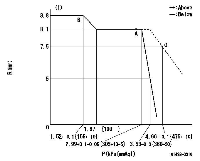
R:Rack position (mm)
P:Negative pressure
(1)Pneumatic governor
----------
----------
----------
----------
Information:
There are two water temperature regulators, one for each cylinder head.1. Drain the coolant from the engine to a level below the water temperature regulators.
Typical Example2. Remove elbow (1). Remove tube and elbow (2). 3. Remove cover assemblies (3). 4. Remove water temperature regulator (4) from each cover assembly. 5. Remove lip-type seal (5) from each cover assembly if a replacement is necessary.6. Check the water temperature regulators. See Specifications Manual SENR6475. The following steps are for the installation of the water temperature regulators. 7. Use Tool (A) to install lip-type seals (5). Install the seals with the lip toward the inside of the covers. Install the seal until it contacts the counterbore in the cover assembly.
If the water temperature regulators are installed incorrectly the engine will over heat.
8. Put clean glycerin on the lip of seal (5), and install water temperature regulator (4) in each cover assembly (3). 9. Install new gaskets (6) and cover assemblies (3).
Typical Example10. Install the gaskets and elbow (1). Put clean engine oil or glycerin on the O-ring seals on tube (2). Install the gasket, tube and elbow (2).11. Fill the cooling system to the correct level. See the Operation & Maintenance Manual.
Have questions with 101492-3310?
Group cross 101492-3310 ZEXEL
Komatsu
101492-3310
9 400 614 433
6130721412
INJECTION-PUMP ASSEMBLY
4D105
4D105