Information injection-pump assembly
BOSCH
9 400 610 546
9400610546
ZEXEL
101492-1221
1014921221
MITSUBISHI
ME080864
me080864
Rating:
Service parts 101492-1221 INJECTION-PUMP ASSEMBLY:
1.
_
5.
AUTOM. ADVANCE MECHANIS
6.
COUPLING PLATE
8.
_
9.
_
11.
Nozzle and Holder
ME080371
12.
Open Pre:MPa(Kqf/cm2)
17.7{180}

15.
NOZZLE SET
Cross reference number
BOSCH
9 400 610 546
9400610546
ZEXEL
101492-1221
1014921221
MITSUBISHI
ME080864
me080864
Zexel num
Bosch num
Firm num
Name
101492-1221
9 400 610 546
ME080864 MITSUBISHI
INJECTION-PUMP ASSEMBLY
4D31T * K 14BC INJECTION PUMP ASSY PE4A,5A, PE
4D31T * K 14BC INJECTION PUMP ASSY PE4A,5A, PE
Calibration Data:
Adjustment conditions
Test oil
1404 Test oil ISO4113 or {SAEJ967d}
1404 Test oil ISO4113 or {SAEJ967d}
Test oil temperature
degC
40
40
45
Nozzle and nozzle holder
105780-8140
Bosch type code
EF8511/9A
Nozzle
105780-0000
Bosch type code
DN12SD12T
Nozzle holder
105780-2080
Bosch type code
EF8511/9
Opening pressure
MPa
17.2
Opening pressure
kgf/cm2
175
Injection pipe
Outer diameter - inner diameter - length (mm) mm 6-2-600
Outer diameter - inner diameter - length (mm) mm 6-2-600
Overflow valve
131424-4620
Overflow valve opening pressure
kPa
255
221
289
Overflow valve opening pressure
kgf/cm2
2.6
2.25
2.95
Tester oil delivery pressure
kPa
157
157
157
Tester oil delivery pressure
kgf/cm2
1.6
1.6
1.6
Direction of rotation (viewed from drive side)
Right R
Right R
Injection timing adjustment
Direction of rotation (viewed from drive side)
Right R
Right R
Injection order
1-3-4-2
Pre-stroke
mm
3.2
3.15
3.25
Beginning of injection position
Drive side NO.1
Drive side NO.1
Difference between angles 1
Cal 1-3 deg. 90 89.5 90.5
Cal 1-3 deg. 90 89.5 90.5
Difference between angles 2
Cal 1-4 deg. 180 179.5 180.5
Cal 1-4 deg. 180 179.5 180.5
Difference between angles 3
Cyl.1-2 deg. 270 269.5 270.5
Cyl.1-2 deg. 270 269.5 270.5
Injection quantity adjustment
Adjusting point
A
Rack position
9.8
Pump speed
r/min
1100
1100
1100
Average injection quantity
mm3/st.
73
72
74
Max. variation between cylinders
%
0
-2.5
2.5
Basic
*
Fixing the rack
*
Injection quantity adjustment_02
Adjusting point
-
Rack position
7.4+-0.5
Pump speed
r/min
500
500
500
Average injection quantity
mm3/st.
8
6.7
9.3
Max. variation between cylinders
%
0
-14
14
Fixing the rack
*
Remarks
Adjust only variation between cylinders; adjust governor according to governor specifications.
Adjust only variation between cylinders; adjust governor according to governor specifications.
Injection quantity adjustment_03
Adjusting point
C
Rack position
-
Pump speed
r/min
100
100
100
Average injection quantity
mm3/st.
60
60
70
Fixing the lever
*
Rack limit
*
Test data Ex:
Governor adjustment
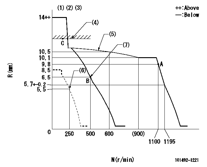
N:Pump speed
R:Rack position (mm)
(1)Target notch: K
(2)Tolerance for racks not indicated: +-0.05mm.
(3)Torque spring does not operate.
(4)RACK LIMIT
(5)The torque control spring must does not have a set force.
(6)Set idle sub-spring
(7)Main spring setting
----------
K=17
----------
----------
K=17
----------
Speed control lever angle
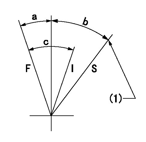
F:Full speed
I:Idle
S:Stop
(1)Rack position = aa
----------
aa=1mm
----------
a=(15deg)+-5deg b=(35deg) c=(22deg)+-5deg
----------
aa=1mm
----------
a=(15deg)+-5deg b=(35deg) c=(22deg)+-5deg
Stop lever angle

N:Pump normal
S:Stop the pump.
----------
----------
a=26.5deg+-5deg b=53deg+-5deg
----------
----------
a=26.5deg+-5deg b=53deg+-5deg
Timing setting

(1)Pump vertical direction
(2)Position of gear mark '3' at No 1 cylinder's beginning of injection
(3)B.T.D.C.: aa
(4)-
----------
aa=16deg
----------
a=(130deg)
----------
aa=16deg
----------
a=(130deg)
Information:
2. Loosen two hose clamps (1).3. Remove hose (2). 4. Remove two bolts (3).5. Remove elbow (5).6. Remove fumes disposal tube (4) for access to the water pump.7. Disconnect coolant conditioner hose (6).8. Remove heater hose (12) (previously removed).9. Loosen hose clamp (15).10. Disconnect lower radiator hose (13).11. Remove two bolts (14) from oil cooler. Check gasket for wear or damage. Replace if necessary.12. Remove four bolts (10).13. Remove water pump cover (11).14. Remove seven long bolts (7).15. Reposition air conditioning lines and oil line (8) after bolts are removed.16. Remove water pump (9). Check seals and O-rings for wear and damage before installation, replace as necessary. For installation of the water pump, reverse the removal steps.17. Fill the cooling system with coolant to correct level. See the Operation & Maintenance Manual.Disassemble Water Pump
*Part of 1P510 Driver Group.Start By:a. remove water pump The water pump seal can be replaced without removing the water pump from the engine. An intermittent leakage of a small amount of coolant from the hole in the water pump housing is not an indication of a water pump seal failure. This is required to provide lubrication for the seal. Replace the water pump seal only if a large amount of leakage or a constant flow of coolant is observed draining from the water pump housing.1. Remove O-ring seal (1) from the adapter.2. Remove adapter (2) from the housing. Remove the O-ring seal from the outside diameter of the adapter.3. Remove bolt (3) and the retainer that hold the impeller on the shaft. 4. Use Tool (A) to remove impeller (4) from the shaft. 5. Remove the spring and seal (5) from the shaft. 6. Remove four bolts (7) from retainer (6) that hold the shaft assembly to the pump housing.7. Remove O-ring seal (8) from the housing. 8. Remove gear and shaft assembly (10) from the housing.9. Remove bolt (9) and the retainer from the shaft assembly. 10. Use a press to remove the shaft assembly from gear (11). Remove the retainer from the shaft assembly. 11. Remove bearing (13), spacer (14) and bearing (12) from the shaft. 12. Remove lip-type seal (15) from the housing.13. Turn the housing over, and remove ceramic ring (16) and the seal.Assemble Water Pump
1. Use 6V1541 Quick Cure Primer to clean shaft (8) and the seal counterbore in the pump housing.2. Install bearing (4), spacer (3) and bearing (2) on shaft (8).3. Put retainer (1) and gear (7) in position on the shaft assembly. Install retainer (6) and bolt (5). 4. Use Tool (A) to install the lip-type seal in the housing as shown. Put a small amount of clean SAE 30 Oil on the lip of the seal. 5. Install a new O-ring seal (10) on the housing.6. Put shaft assembly (9) in position in the housing. Install the bolts that hold the retainer to the housing.
Clean water only is permitted for use as a lubricant for assistance at installation. Do not damage or put hands on
Have questions with 101492-1221?
Group cross 101492-1221 ZEXEL
Mitsubishi
Mitsubishi
Mitsubishi
101492-1221
9 400 610 546
ME080864
INJECTION-PUMP ASSEMBLY
4D31T
4D31T