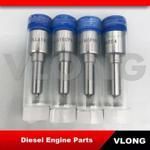
Information injection-pump assembly
BOSCH
9 400 614 423
9400614423
ZEXEL
101492-1061
1014921061
MITSUBISHI
ME017863
me017863

Rating:
Service parts 101492-1061 INJECTION-PUMP ASSEMBLY:
1.
_
5.
AUTOM. ADVANCE MECHANIS
6.
COUPLING PLATE
8.
_
9.
_
11.
Nozzle and Holder
ME019368
12.
Open Pre:MPa(Kqf/cm2)
17.7{180}
15.
NOZZLE SET
Cross reference number
Zexel num
Bosch num
Firm num
Name
9 400 614 423
ME017863 MITSUBISHI
INJECTION-PUMP ASSEMBLY
4D31T K 14BC INJECTION PUMP ASSY PE4A,5A, PE
4D31T K 14BC INJECTION PUMP ASSY PE4A,5A, PE
Information:
Start By:a. remove oil pump 1. Check each connecting rod cap for its location on the crankshaft. Each cap must have a number (1) which is the same as the number on the connecting rod. Do not mix bearings.2. Turn the crankshaft until two of the pistons are at bottom center.3. Remove connecting rod caps (2). Remove the lower bearing from the connecting rod caps.4. Push the connecting rods away from the crankshaft and remove the upper bearings from the connecting rods.
Be careful not to damage the crankshaft journals. Do not turn the crankshaft while any of the connecting rod caps are removed.
5. Install the upper bearings in connecting rods. put clean engine oil on the bearings and on the crankshaft journals. Slowly pull the connecting rods on the crankshaft.6. Put clean oil on the lower bearings. Install the lower bearings in the connecting rod caps. Be sure tab (3) on the back of the bearings fits in the groove of the caps and connecting rods. 7. Check the bearing clearance with Plastigage (A) as follows:a. Put clean oil on the threads of bolts (4). Install caps (5), Tool (A) and nuts finger tight.b. Tighten each nut (6) to a torque of 80 8 N m (60 6 lb ft).c. Put a mark across the nuts and bolts. Tighten the nuts 120 degrees more. 8. Remove caps (5) and Plastigage (A). Make sure the connecting rod bearing caps are installed with their identification number in arrangement with the connecting rod number.
Do not use an impact wrench to tighten the nuts the additional 120 degrees.
9. Measure the thickness of the Plastigage to find the bearing clearance. the clearance for new bearings must be 0.071 to 0.168 mm (.0028 to .0066 in). The maximum clearance for used bearings is 0.25 mm (0.010 in).10. Install caps (5). Tighten nuts (6) to a torque of 80 8 N m (60 6 lb ft). Tighten the nuts 120 degrees more.11. Do Steps 1 through 10 for the other connecting rod bearings.End By:a. install oil pump
