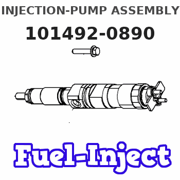
Information injection-pump assembly
BOSCH
9 400 614 413
9400614413
ZEXEL
101492-0890
1014920890
ISUZU
8971903730
8971903730
Rating:
Service parts 101492-0890 INJECTION-PUMP ASSEMBLY:
1.
_
5.
AUTOM. ADVANCE MECHANIS
6.
COUPLING PLATE
8.
_
9.
_
11.
Nozzle and Holder
8-94122-262-5
12.
Open Pre:MPa(Kqf/cm2)
18.1{185}
15.
NOZZLE SET
Cross reference number
BOSCH
9 400 614 413
9400614413
ZEXEL
101492-0890
1014920890
ISUZU
8971903730
8971903730
Zexel num
Bosch num
Firm num
Name
101492-0890
9 400 614 413
8971903730 ISUZU
INJECTION-PUMP ASSEMBLY
4JA1 K 14BC INJECTION PUMP ASSY PE4A,5A, PE
4JA1 K 14BC INJECTION PUMP ASSY PE4A,5A, PE
Calibration Data:
Adjustment conditions
Test oil
1404 Test oil ISO4113 or {SAEJ967d}
1404 Test oil ISO4113 or {SAEJ967d}
Test oil temperature
degC
40
40
45
Nozzle and nozzle holder
105780-8140
Bosch type code
EF8511/9A
Nozzle
105780-0000
Bosch type code
DN12SD12T
Nozzle holder
105780-2080
Bosch type code
EF8511/9
Opening pressure
MPa
17.2
Opening pressure
kgf/cm2
175
Injection pipe
Outer diameter - inner diameter - length (mm) mm 6-2-600
Outer diameter - inner diameter - length (mm) mm 6-2-600
Overflow valve
131424-0820
Overflow valve opening pressure
kPa
127
107
147
Overflow valve opening pressure
kgf/cm2
1.3
1.1
1.5
Tester oil delivery pressure
kPa
157
157
157
Tester oil delivery pressure
kgf/cm2
1.6
1.6
1.6
Direction of rotation (viewed from drive side)
Left L
Left L
Injection timing adjustment
Direction of rotation (viewed from drive side)
Left L
Left L
Injection order
1-3-4-2
Pre-stroke
mm
3.3
3.25
3.35
Beginning of injection position
Drive side NO.1
Drive side NO.1
Difference between angles 1
Cal 1-3 deg. 90 89.5 90.5
Cal 1-3 deg. 90 89.5 90.5
Difference between angles 2
Cal 1-4 deg. 180 179.5 180.5
Cal 1-4 deg. 180 179.5 180.5
Difference between angles 3
Cyl.1-2 deg. 270 269.5 270.5
Cyl.1-2 deg. 270 269.5 270.5
Injection quantity adjustment
Adjusting point
A
Rack position
10.8
Pump speed
r/min
1200
1200
1200
Average injection quantity
mm3/st.
48.5
47.5
49.5
Max. variation between cylinders
%
0
-2.5
2.5
Basic
*
Fixing the lever
*
Injection quantity adjustment_02
Adjusting point
-
Rack position
9+-0.5
Pump speed
r/min
540
540
540
Average injection quantity
mm3/st.
11.4
9.4
13.4
Max. variation between cylinders
%
0
-15
15
Fixing the rack
*
Remarks
Adjust only variation between cylinders; adjust governor according to governor specifications.
Adjust only variation between cylinders; adjust governor according to governor specifications.
Test data Ex:
Governor adjustment
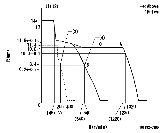
N:Pump speed
R:Rack position (mm)
(1)Target notch: K
(2)Tolerance for racks not indicated: +-0.05mm.
(3)Set idle sub-spring
(4)Main spring setting
----------
K=15
----------
----------
K=15
----------
Speed control lever angle
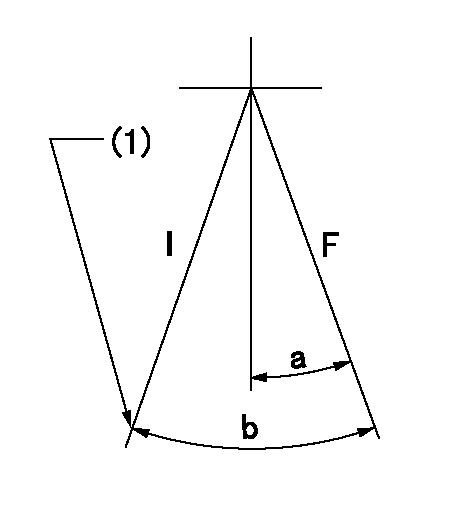
F:Full speed
I:Idle
(1)Stopper bolt setting
----------
----------
a=10deg+-5deg b=21deg+-5deg
----------
----------
a=10deg+-5deg b=21deg+-5deg
Stop lever angle
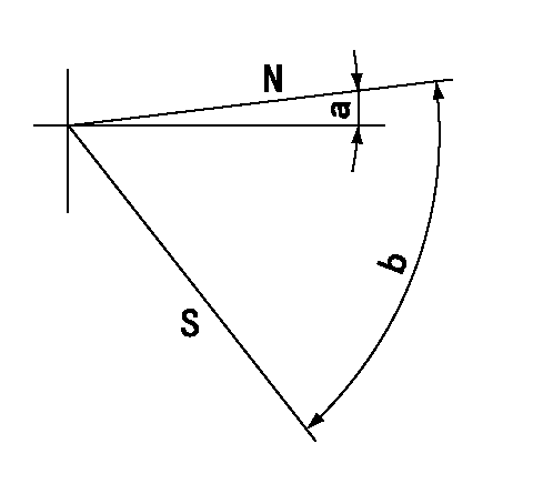
N:Pump normal
S:Stop the pump.
----------
----------
a=0deg+-5deg b=53deg+-5deg
----------
----------
a=0deg+-5deg b=53deg+-5deg
Timing setting
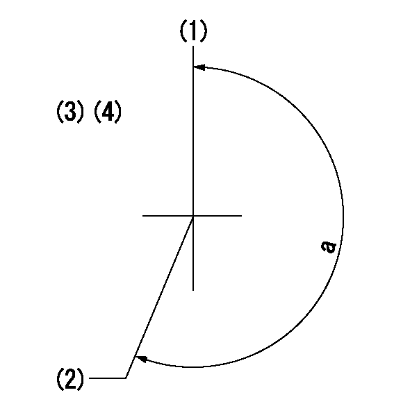
(1)Pump vertical direction
(2)Position of gear mark 'V' at No 1 cylinder's beginning of injection
(3)B.T.D.C.: aa
(4)-
----------
aa=17deg
----------
a=(210deg)
----------
aa=17deg
----------
a=(210deg)
Information:
Start By:a. remove flywheel housing 1. Loosen four bolts (1) approximately 6.4 mm (.25 in). Use Tool (A) to loosen camshaft rear gear (2) from the camshaft.2. Remove Tool (A) and four bolts (1).
If balancer gear (3) is in a position similar to that shown in the picture, the weight on balancer gear (3) will turn down when the camshaft rear gear is removed. To prevent personal injury, hold balancer gear (3) when camshaft rear gear (2) is removed.
3. Remove camshaft rear gear (2). 4. Remove bolt (4), plate (5) and balancer gear (3).5. Inspect the bearing in balancer gear (3). The inside diameter (bore) of a new bearing must be 50.853 to 50.950 mm (2.0021 to 2.0059 in). 6. Use Tooling (B) and a press to remove the bearing from balancer gear (3). 7. Inspect shaft (7) for wear or damage. The outside diameter (new) of shaft (7) must be 50.787 to 50.813 mm (1.9995 to 2.0005 in).8. If a replacement of shaft (7) is necessary, remove bolts (6) and shaft (7) from the cylinder block.Install Camshaft Rear Gear & Balancer
1. Install shaft (7) and four bolts (6) on the cylinder block. 2. Use Tooling (A) to install the bearing in balancer gear (3). Install the bearing so that the bearing joint is on the weight side of the gear within 20 degrees of the centerline as shown. Install the bearing so that it is 1.3 mm (.05 in) from the opposite surface on balancer gear (3). 3. Put clean engine oil on the inside diameter of the bearing in the balancer gear. Install balancer gear (3) and plate (5). Make sure the side of the balancer gear with the weight is toward the cylinder block. Install the bolt (4) that holds the balancer gear in position on the shaft. Check to make sure that there is 0.15 to 0.36 mm (.006 to .014 in) end play between the balancer gear and the shaft.
Be sure the timing "V" marks (8) are aligned when the camshaft rear gear is installed on the camshaft.
4. Engage camshaft rear gear (2) with the dowel on the camshaft. Install bolts (1).5. Tighten bolts (1) to a torque of 23 to 31 N m (17 to 23 lb ft).End By:a. install flywheel housing
Have questions with 101492-0890?
Group cross 101492-0890 ZEXEL
Isuzu
101492-0890
9 400 614 413
8971903730
INJECTION-PUMP ASSEMBLY
4JA1
4JA1