Information injection-pump assembly
BOSCH
9 400 610 538
9400610538
ZEXEL
101492-0751
1014920751
ISUZU
8971392241
8971392241
Rating:
Service parts 101492-0751 INJECTION-PUMP ASSEMBLY:
1.
_
5.
AUTOM. ADVANCE MECHANIS
6.
COUPLING PLATE
8.
_
9.
_
11.
Nozzle and Holder
8-97134-524-0
12.
Open Pre:MPa(Kqf/cm2)
18.1{185}

15.
NOZZLE SET
Cross reference number
BOSCH
9 400 610 538
9400610538
ZEXEL
101492-0751
1014920751
ISUZU
8971392241
8971392241
Zexel num
Bosch num
Firm num
Name
101492-0751
9 400 610 538
8971392241 ISUZU
INJECTION-PUMP ASSEMBLY
4JB1 K 14BC INJECTION PUMP ASSY PE4A,5A, PE
4JB1 K 14BC INJECTION PUMP ASSY PE4A,5A, PE
Calibration Data:
Adjustment conditions
Test oil
1404 Test oil ISO4113 or {SAEJ967d}
1404 Test oil ISO4113 or {SAEJ967d}
Test oil temperature
degC
40
40
45
Nozzle and nozzle holder
105780-8140
Bosch type code
EF8511/9A
Nozzle
105780-0000
Bosch type code
DN12SD12T
Nozzle holder
105780-2080
Bosch type code
EF8511/9
Opening pressure
MPa
17.2
Opening pressure
kgf/cm2
175
Injection pipe
Outer diameter - inner diameter - length (mm) mm 6-2-600
Outer diameter - inner diameter - length (mm) mm 6-2-600
Overflow valve
131424-0820
Overflow valve opening pressure
kPa
127
107
147
Overflow valve opening pressure
kgf/cm2
1.3
1.1
1.5
Tester oil delivery pressure
kPa
157
157
157
Tester oil delivery pressure
kgf/cm2
1.6
1.6
1.6
Direction of rotation (viewed from drive side)
Left L
Left L
Injection timing adjustment
Direction of rotation (viewed from drive side)
Left L
Left L
Injection order
1-3-4-2
Pre-stroke
mm
3.3
3.25
3.35
Rack position
Point A R=A
Point A R=A
Beginning of injection position
Drive side NO.1
Drive side NO.1
Difference between angles 1
Cal 1-3 deg. 90 89.5 90.5
Cal 1-3 deg. 90 89.5 90.5
Difference between angles 2
Cal 1-4 deg. 180 179.5 180.5
Cal 1-4 deg. 180 179.5 180.5
Difference between angles 3
Cyl.1-2 deg. 270 269.5 270.5
Cyl.1-2 deg. 270 269.5 270.5
Injection quantity adjustment
Adjusting point
A
Rack position
8.3
Pump speed
r/min
1100
1100
1100
Average injection quantity
mm3/st.
59
58
60
Max. variation between cylinders
%
0
-2.5
2.5
Basic
*
Fixing the lever
*
Injection quantity adjustment_02
Adjusting point
-
Rack position
6.6+-0.5
Pump speed
r/min
500
500
500
Average injection quantity
mm3/st.
11.5
9.5
13.5
Max. variation between cylinders
%
0
-15
15
Fixing the rack
*
Remarks
Adjust only variation between cylinders; adjust governor according to governor specifications.
Adjust only variation between cylinders; adjust governor according to governor specifications.
Injection quantity adjustment_03
Adjusting point
D
Rack position
14++
Pump speed
r/min
100
100
100
Average injection quantity
mm3/st.
70
70
102
Fixing the lever
*
Test data Ex:
Governor adjustment
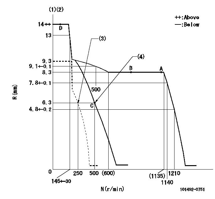
N:Pump speed
R:Rack position (mm)
(1)Target notch: K
(2)Tolerance for racks not indicated: +-0.05mm.
(3)Set idle sub-spring
(4)Main spring setting
----------
K=7
----------
----------
K=7
----------
Speed control lever angle
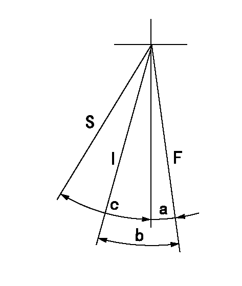
F:Full speed
I:Idle
S:Stop
----------
----------
a=4deg+-5deg b=16deg+-5deg c=35deg+-3deg
----------
----------
a=4deg+-5deg b=16deg+-5deg c=35deg+-3deg
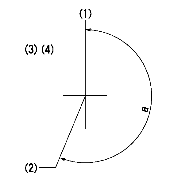
Stop lever angle
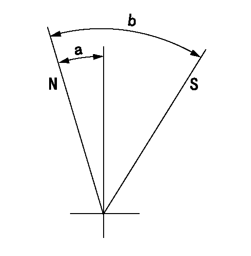
N:Pump normal
S:Stop the pump.
----------
----------
a=2.5deg+-5deg b=53deg+-5deg
----------
----------
a=2.5deg+-5deg b=53deg+-5deg
Timing setting
(1)Pump vertical direction
(2)Position of gear mark 'V' at No 1 cylinder's beginning of injection
(3)B.T.D.C.: aa
(4)-
----------
aa=14deg
----------
a=(210deg)
----------
aa=14deg
----------
a=(210deg)
Information:
2. Loosen clamp (1).3. Remove two bolts (2).4. Remove two bolts (3) and washers.5. Remove water pump (4) and the gasket. When installing replace the gasket. Make sure all gasket surfaces are clean and free of dirt. For installation of the water pump, reverse the removal steps.6. Fill the radiator with coolant to the proper level. See the Operation & Maintenance Manual.Disassemble & Assemble Water Pump
The following tools are needed for disassembly. Start By:a. remove water pump 1. Remove bolt (15) and the washer. Remove bearing (12) and gear (10) as a unit.2. Use Tool (A), (C) and a press, and remove bearing (12) from gear (10).3. Remove snap ring (8) with Tool (B).4. Remove two bolts (1), the washers, cover (14) and gasket (2) from water pump housing (18).5. Loosen bolt (13) approximately 6.4 mm (.25 in). Hit the bolt with a soft hammer to loosen impeller (16) from shaft (9).6. Remove bolt (13), washer (11), impeller (16), spring (3) and seal assembly (4) from shaft (9).7. Remove bearing (7) and shaft (9) as a unit.8. Use Tool (A), (C) and a press to remove bearing (7) from shaft (9).9. Remove ceramic seal (5) and seal (17) from water pump housing (18).10. Use Tool (C) to remove lip-type seal (6) from the water pump housing. The following steps are for assembly of the water pump. The following tools are needed for assembly. 11. Install lip-type seal (6) in water pump housing (18) with Tool (C). The lip of the seal must be toward the bearings. Put clean engine oil on the lip of the seal.12. Install shaft (9) in bearing (7) with a press.13. Install shaft (9) and bearing (7) as a unit in water pump housing (18).14. Install snap ring (8) with Tool (B).
Clean water only is permitted for use as a lubricant for assembly. Do not damage or put hands on the wear surface of the carbon ring or the ceramic ring. Install the ceramic ring with the smoothest face of the ring toward the carbon seal assembly.
15. Put ceramic ring (5) in position in seal (17). Use hand pressure and Tool (D) to install the ceramic ring.16. Remove spring (3) from seal assembly (4). Use hand pressure and Tool (D) to install the seal assembly. Push seal assembly (4) on shaft (9) until it makes light contact with ceramic ring (5).17. Install spring (3) on seal assembly (4). Put impeller (16) in position on shaft (9), and install washer (11) and bolt (13) that hold it. Tighten bolt (13) to a torque of 38.0 1.5 N m (28 1 lb ft).18. Put gasket (2) and cover (14) in position on water pump housing (18). Install the two washers and bolts (1) that hold them.19. Install bearing (12) on gear (10) with a press.20. Position gear (10) and bearing (12) as a unit on shaft (9). Install the washer and bolt (15) that hold them together. Tighten bolt (15) to a torque of
Have questions with 101492-0751?
Group cross 101492-0751 ZEXEL
Isuzu
Isuzu
Isuzu
101492-0751
9 400 610 538
8971392241
INJECTION-PUMP ASSEMBLY
4JB1
4JB1