Information injection-pump assembly
ZEXEL
101492-0350
1014920350
ISUZU
8943224890
8943224890
Rating:
Cross reference number
ZEXEL
101492-0350
1014920350
ISUZU
8943224890
8943224890
Zexel num
Bosch num
Firm num
Name
Calibration Data:
Adjustment conditions
Test oil
1404 Test oil ISO4113 or {SAEJ967d}
1404 Test oil ISO4113 or {SAEJ967d}
Test oil temperature
degC
40
40
45
Nozzle and nozzle holder
105780-8140
Bosch type code
EF8511/9A
Nozzle
105780-0000
Bosch type code
DN12SD12T
Nozzle holder
105780-2080
Bosch type code
EF8511/9
Opening pressure
MPa
17.2
Opening pressure
kgf/cm2
175
Injection pipe
Outer diameter - inner diameter - length (mm) mm 6-2-600
Outer diameter - inner diameter - length (mm) mm 6-2-600
Tester oil delivery pressure
kPa
157
157
157
Tester oil delivery pressure
kgf/cm2
1.6
1.6
1.6
Direction of rotation (viewed from drive side)
Right R
Right R
Injection timing adjustment
Direction of rotation (viewed from drive side)
Right R
Right R
Injection order
1-3-4-2
Pre-stroke
mm
3.4
3.35
3.45
Beginning of injection position
Drive side NO.1
Drive side NO.1
Difference between angles 1
Cal 1-3 deg. 90 89.5 90.5
Cal 1-3 deg. 90 89.5 90.5
Difference between angles 2
Cal 1-4 deg. 180 179.5 180.5
Cal 1-4 deg. 180 179.5 180.5
Difference between angles 3
Cyl.1-2 deg. 270 269.5 270.5
Cyl.1-2 deg. 270 269.5 270.5
Injection quantity adjustment
Adjusting point
A
Rack position
10.9
Pump speed
r/min
1050
1050
1050
Average injection quantity
mm3/st.
54.6
53.6
55.6
Max. variation between cylinders
%
0
-2
2
Basic
*
Fixing the lever
*
Injection quantity adjustment_02
Adjusting point
C
Rack position
8.3+-0.5
Pump speed
r/min
325
325
325
Average injection quantity
mm3/st.
8
6.5
9.5
Max. variation between cylinders
%
0
-14
14
Fixing the rack
*
Test data Ex:
Governor adjustment
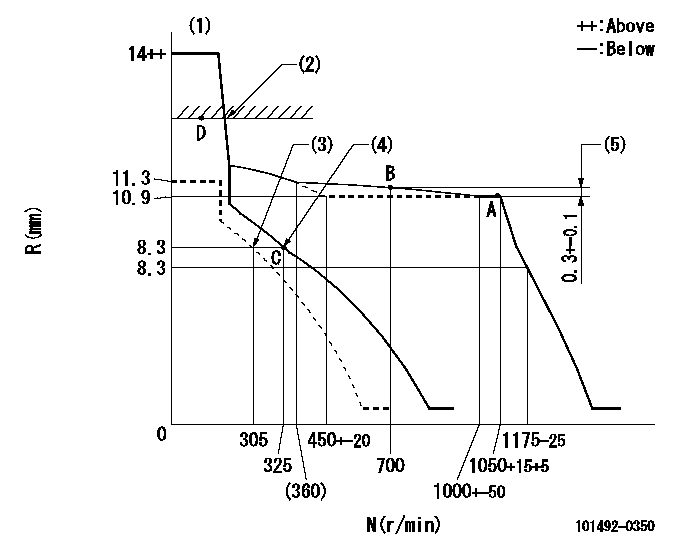
N:Pump speed
R:Rack position (mm)
(1)Target notch: K
(2)RACK LIMIT: RAL
(3)Set idle sub-spring
(4)Main spring setting
(5)Rack difference from N = N1
----------
K=13 RAL=13.4+0.2mm N1=1050r/min
----------
----------
K=13 RAL=13.4+0.2mm N1=1050r/min
----------
Speed control lever angle

F:Full speed
I:Idle
(1)Stopper bolt setting
----------
----------
a=11deg+-5deg b=19deg+-5deg
----------
----------
a=11deg+-5deg b=19deg+-5deg
Stop lever angle

N:Pump normal
S:Stop the pump.
----------
----------
a=19deg+-5deg b=53deg+-5deg
----------
----------
a=19deg+-5deg b=53deg+-5deg
Timing setting

(1)Pump vertical direction
(2)Position of gear mark 'CC' at No 1 cylinder's beginning of injection
(3)B.T.D.C.: aa
(4)-
----------
aa=16deg
----------
a=(90deg)
----------
aa=16deg
----------
a=(90deg)
Information:
(1) Balancer unit idler gear: Inside diameter of gear bore ... 47.635 to 47.650 mm (1.8754 to 1.8760 in)Outside diameter of gear bearing ... 47.63 mm (1.875 in)Inside diameter of gear bearing ... 38.1 mm (1.50 in)Outside diameter of idler gear hub ... 38.090 to 38.100 mm (1.4996 to 1.5000 in)Idler gear end play ... 0.08 to 0.23 mm (.003 to .009 in)Torque for idler gear bolt ... 75 N m (55 lb ft)(2) Idler gear thrust washer: Thrust washer thickness ... 4.14 to 4.29 mm (.163 to .169 in)Outside diameter of thrust washer ... 59.00 mm (2.323 in)Inside diameter of thrust washer ... 19.99 mm (0.787 in)
Be sure thread lock does not get on gear shaft drive needle bearing or it can cause the needle bearing to fail.
(3) Put 9S3263 Thread Lock on balance weight drive gear splines and threads for nut (3). Torque for nut ... 85 N m (65 lb ft)Diameter of balance weight drive gear splines ... 16.51 to 16.54 mm (.650 to .651 in)
If the oil transfer cover plate arrow points to the wrong side of the engine, the engine will seize due to the lack of lubrication.
(4) Torque for end cover bolts ... 55 N m (40 lb ft)(5) Install oil transfer cover plate with arrow pointing to side of engine that oil filter is on. Torque for cover plate bolts ... 30 N m (24 lb ft)(6) Gear shaft drive: Diameter of drive shaft at front bearing ... 28.55 to 28.58 mm (1.124 to 1.125 in)Diameter of drive shaft at rear bearing ... 23.77 to 23.80 mm (.936 to .937 in)Diameter of oil pump drive splines ... 28.55 to 28.58 mm (1.124 to 1.125 in)Diameter of front bearing bore ... 34.90 to 34.93 mm (1.374 to 1.375 in)Outside diameter of front bearing ... 34.920 mm (1.3748 in)Inside diameter of front bearing ... 28.58 mm (1.125 in)Diameter of rear bearing bore ... 45.72 to 45.85 mm (1.800 to 1.805 in)Outside diameter of rear bearing ... 30.00 mm (1.181 in)Inside diameter of rear bearing ... 23.80 mm (.937 in)End play of drive shaft ... 0.170 to 0.348 mm (.0067 to .0137 in)(7) Drive shaft front bearing dimension below front face of frame ... 2.49 to 3.00 mm (.098 to .118 in)(8) Length of drive shaft between rear bearing and front face of shaft ... 130.20 to 131.17 mm (5.126 to 5.164 in)(9) Drive shaft rear bearing dimension below machined surface ... 0.201 to 2.997 mm (.0079 to .1180 in) (10) Balance weights: Diameter of balance frame and end bushing bores ... 42.06 to 42.09 mm (1.656 to 1.657 in)Outside diameter of balance frame and end frame bushings ... 42.2 mm (1.66 in)Inside diameter of balance frame and end frame bushings ... 38.13 to 38.18 mm (1.501 to 1.503 in)Shaft diameter of balance weights ... 38.05 to 38.07 mm (1.498 to 1.499 in)Clearance between balance weight shafts and bushings ... 0.064