Information injection-pump assembly
ZEXEL
101492-0330
1014920330
ISUZU
8944302531
8944302531
Rating:
Cross reference number
ZEXEL
101492-0330
1014920330
ISUZU
8944302531
8944302531
Zexel num
Bosch num
Firm num
Name
Calibration Data:
Adjustment conditions
Test oil
1404 Test oil ISO4113 or {SAEJ967d}
1404 Test oil ISO4113 or {SAEJ967d}
Test oil temperature
degC
40
40
45
Nozzle and nozzle holder
105780-8140
Bosch type code
EF8511/9A
Nozzle
105780-0000
Bosch type code
DN12SD12T
Nozzle holder
105780-2080
Bosch type code
EF8511/9
Opening pressure
MPa
17.2
Opening pressure
kgf/cm2
175
Injection pipe
Outer diameter - inner diameter - length (mm) mm 6-2-600
Outer diameter - inner diameter - length (mm) mm 6-2-600
Overflow valve
131424-0820
Overflow valve opening pressure
kPa
127
107
147
Overflow valve opening pressure
kgf/cm2
1.3
1.1
1.5
Tester oil delivery pressure
kPa
157
157
157
Tester oil delivery pressure
kgf/cm2
1.6
1.6
1.6
Direction of rotation (viewed from drive side)
Left L
Left L
Injection timing adjustment
Direction of rotation (viewed from drive side)
Left L
Left L
Injection order
1-3-4-2
Pre-stroke
mm
3.3
3.25
3.35
Beginning of injection position
Drive side NO.1
Drive side NO.1
Difference between angles 1
Cal 1-3 deg. 90 89.5 90.5
Cal 1-3 deg. 90 89.5 90.5
Difference between angles 2
Cal 1-4 deg. 180 179.5 180.5
Cal 1-4 deg. 180 179.5 180.5
Difference between angles 3
Cyl.1-2 deg. 270 269.5 270.5
Cyl.1-2 deg. 270 269.5 270.5
Injection quantity adjustment
Adjusting point
A
Rack position
10.4
Pump speed
r/min
1250
1250
1250
Average injection quantity
mm3/st.
41.4
40.4
42.4
Max. variation between cylinders
%
0
-2.5
2.5
Basic
*
Fixing the lever
*
Injection quantity adjustment_02
Adjusting point
B
Rack position
8.8+-0.5
Pump speed
r/min
450
450
450
Average injection quantity
mm3/st.
11.4
9.4
13.4
Max. variation between cylinders
%
0
-15
15
Fixing the rack
*
Test data Ex:
Governor adjustment
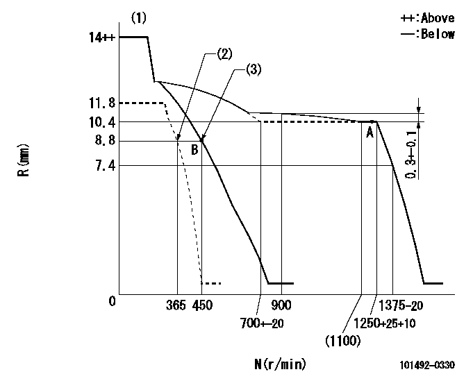
N:Pump speed
R:Rack position (mm)
(1)Target notch: K
(2)Set idle sub-spring
(3)Main spring setting
----------
K=13
----------
----------
K=13
----------
Speed control lever angle
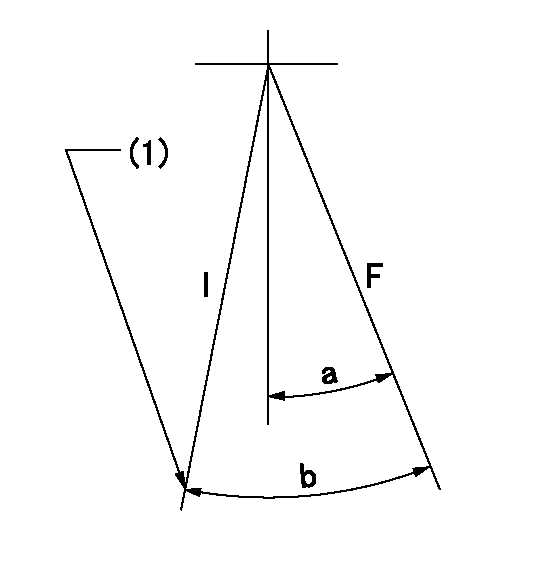
F:Full speed
I:Idle
(1)Stopper bolt setting
----------
----------
a=16deg+-5deg b=27deg+-5deg
----------
----------
a=16deg+-5deg b=27deg+-5deg
Stop lever angle
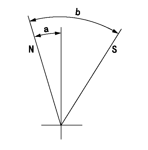
N:Pump normal
S:Stop the pump.
----------
----------
a=2.5deg+-5deg b=53deg+-5deg
----------
----------
a=2.5deg+-5deg b=53deg+-5deg
Timing setting
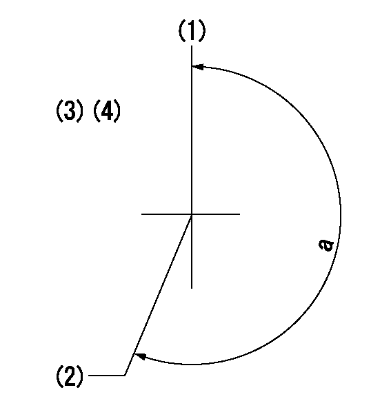
(1)Pump vertical direction
(2)Position of gear mark 'V' at No 1 cylinder's beginning of injection
(3)B.T.D.C.: aa
(4)-
----------
aa=17deg
----------
a=(200deg)
----------
aa=17deg
----------
a=(200deg)
Information:
4.236 Five Ring Piston(1) First (top) compression ring: Width of compression ring ... 2.357 to 2.383 mm (.0928 to .0938 in)Clearance between ends of ring installed in cylinder liner that has no wear ... 0.41 to 0.86 mm (.016 to .034 in)(2) Second and third compression rings: Width of compression rings ... 2.357 to 2.383 mm (.0928 to .0938 in)Clearance between ends of each ring installed in cylinder liner that has no wear ... 0.30 to 0.76 mm (.012 to .030 in)(3), (4) Fourth and fifth oil rings: Width of oil rings ... 6.32 to 6.35 mm (.249 to .250 in)Clearance between ends of each ring installed in cylinder liner that has no wear ... 0.30 to 0.76 mm (.012 to .030 in)(5), (6), (7) Width of each groove for compression rings ... 2.431 to 2.456 (.0957 to .0967 in) Ring clearance in the groove ... 0.048 to 0.099 mm (.0019 to .0039)(8), (11) Width of each groove for oil rings ... 6.414 to 6.439 mm (.2525 to .2535 in) Ring clearance in the groove ... 0.064 to 0.114 mm (.0025 to .0045 in)(9) Diameter of piston pin (new) ... 34.920 to 34.93 mm (1.3748 to 1.375 in)(10) Bore in piston for pin ... 34.9212 to