Information injection-pump assembly
ZEXEL
101492-0171
1014920171
ISUZU
8941701342
8941701342

Rating:
Cross reference number
ZEXEL
101492-0171
1014920171
ISUZU
8941701342
8941701342
Zexel num
Bosch num
Firm num
Name
Calibration Data:
Adjustment conditions
Test oil
1404 Test oil ISO4113 or {SAEJ967d}
1404 Test oil ISO4113 or {SAEJ967d}
Test oil temperature
degC
40
40
45
Nozzle and nozzle holder
105780-8140
Bosch type code
EF8511/9A
Nozzle
105780-0000
Bosch type code
DN12SD12T
Nozzle holder
105780-2080
Bosch type code
EF8511/9
Opening pressure
MPa
17.2
Opening pressure
kgf/cm2
175
Injection pipe
Outer diameter - inner diameter - length (mm) mm 6-2-600
Outer diameter - inner diameter - length (mm) mm 6-2-600
Overflow valve
131424-0820
Overflow valve opening pressure
kPa
127
107
147
Overflow valve opening pressure
kgf/cm2
1.3
1.1
1.5
Tester oil delivery pressure
kPa
157
157
157
Tester oil delivery pressure
kgf/cm2
1.6
1.6
1.6
Direction of rotation (viewed from drive side)
Left L
Left L
Injection timing adjustment
Direction of rotation (viewed from drive side)
Left L
Left L
Injection order
1-3-4-2
Pre-stroke
mm
3.3
3.25
3.35
Beginning of injection position
Drive side NO.1
Drive side NO.1
Difference between angles 1
Cal 1-3 deg. 90 89.5 90.5
Cal 1-3 deg. 90 89.5 90.5
Difference between angles 2
Cal 1-4 deg. 180 179.5 180.5
Cal 1-4 deg. 180 179.5 180.5
Difference between angles 3
Cyl.1-2 deg. 270 269.5 270.5
Cyl.1-2 deg. 270 269.5 270.5
Injection quantity adjustment
Adjusting point
A
Rack position
10.3
Pump speed
r/min
1250
1250
1250
Average injection quantity
mm3/st.
40
39
41
Max. variation between cylinders
%
0
-2.5
2.5
Basic
*
Fixing the lever
*
Injection quantity adjustment_02
Adjusting point
B
Rack position
8.6+-0.5
Pump speed
r/min
425
425
425
Average injection quantity
mm3/st.
8
6
10
Max. variation between cylinders
%
0
-15
15
Fixing the rack
*
Test data Ex:
Governor adjustment
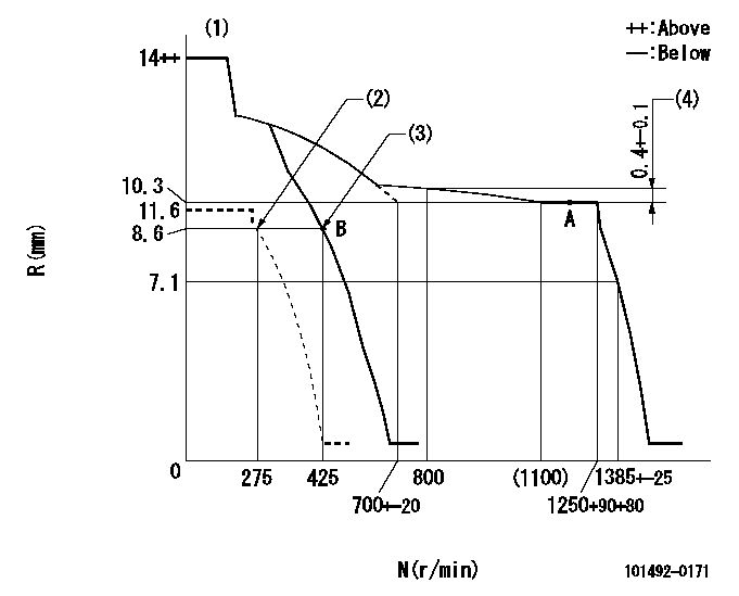
N:Pump speed
R:Rack position (mm)
(1)Target notch: K
(2)Set idle sub-spring
(3)Main spring setting
(4)Rack difference from N = N1
----------
K=7 N1=1250r/min
----------
----------
K=7 N1=1250r/min
----------
Speed control lever angle
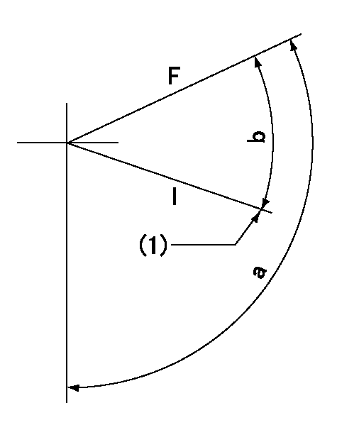
F:Full speed
I:Idle
(1)Stopper bolt setting
----------
----------
a=112deg+-5deg b=29deg+-5deg
----------
----------
a=112deg+-5deg b=29deg+-5deg
Stop lever angle
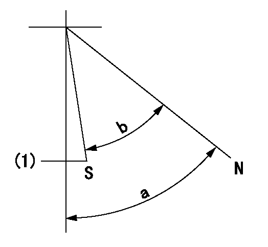
N:Pump normal
S:Stop the pump.
(1)At shipping
----------
----------
a=83deg+-5deg b=53deg+-5deg
----------
----------
a=83deg+-5deg b=53deg+-5deg
Timing setting
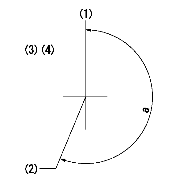
(1)Pump vertical direction
(2)Position of gear mark 'V' at No 1 cylinder's beginning of injection
(3)B.T.D.C.: aa
(4)-
----------
aa=17deg
----------
a=(200deg)
----------
aa=17deg
----------
a=(200deg)
Information:
Tighten locknuts (A) on rod ends to ... 12 4 N m (9 3 lb ft)With governor at High Idle, install lever (B) on governor shaft at an angle from vertical of ... 20 5°Dimension (C) approximately ... 438.0 mm (17.25 in)Dimension (D) approximately ... 597.0 mm (23.50 in)Dimension (E) approximately ... 610.0 mm (24.00 in)Dimension (F) approximately ... 100.00 mm (3.94 in)Dimension (G) ... 1.5 mm (.06 in)Adjust bolt (H) to get dimension (F) with engine at High IdleAdjust setscrew (J) so that engine speed is 985 50 rpm with decelerator pedal depressed. Check High Idle speed after adjustment.After linkage has been adjusted, move control lever to High Idle and adjust setscrew (K) to get dimension (G).D7G With Direct Drive Transmission & 571G Pipelayer
Tighten locknuts (A) on ends to ... 12 4 N m (9 3 lb ft)With governor at High Idle, install lever (B) on governor shaft at an angle from vertical of ... 20 5°Dimension (C) approximately ... 438.0 mm (17.25 in)Dimension (D) approximately ... 597.0 mm (23.50 in)572G Pipelayer
Tighten locknuts (A) on rod ends to ... 12 4 N m (9 3 lb ft)With governor at High Idle, install lever (B) on governor shaft at an angle from vertical of ... 5° 5°Dimension (C) approximately ... 726.4 mm (28.6 in)Dimension (D) approximately ... 683.3 mm (26.9 in)7G5554 Control Group (D6H)
1. Tighten locknuts (A) on rod ends to ... 14 4 N m (10 3 lb ft)2. Align the timing mark on shaft (B) with centerline of sawcut on lever (C).3. Dimension (D) approximately ... 508 mm (20 in)4. With governor control lever in a vertical position, angle (E) ... 32° 5°3T4347 Control Group (D6H)
1. Tighten locknuts (A) on rod ends to ... 14 4 N m (10 3 lb ft)2. Align the timing mark on shaft (B) with centerline of sawcut on lever (C).3. Dimension (D) approximately ... 508 mm (20 in)4. With governor control lever in a vertical position, angle (E) ... 32° 5°6T3303 Control Group (D7H)
1. Tighten locknuts (A) on rod ends to ... 12 4 N m (9 3 lb ft)2. Align the timing mark on shaft (B) with centerline of sawcut on lever (C).3. With governor control lever in a vertical position, angle (E) ... 32° 5°8P3126 Control Group (D5B SA)
1. With control lever (1) in high idle position Dimension (A) approximately ... 495.0 mm (19.5 in)Dimension (B) approximately ... 786.0 mm (30.9 in)Angle (C) from vertical ... 10° 5°2. Tighten locknuts (2) on rod ends to ... 25 7 N m (18 5 lb ft)3. Tighten locknuts (3) on rod ends to ... 12 4 N m (9 3 lb ft)9W3764 Control Group (D6D SA)
1. With control lever (1) in high idle position Dimension (A) approximately ... 495.0 3.0 mm (19.5 .1 in)Dimension (B) approximately ... 735.0 mm (28.9 in)Angle (C) from vertical