Information injection-pump assembly
ZEXEL
101492-0170
1014920170
ISUZU
8941701341
8941701341

Rating:
Cross reference number
ZEXEL
101492-0170
1014920170
ISUZU
8941701341
8941701341
Zexel num
Bosch num
Firm num
Name
Calibration Data:
Adjustment conditions
Test oil
1404 Test oil ISO4113 or {SAEJ967d}
1404 Test oil ISO4113 or {SAEJ967d}
Test oil temperature
degC
40
40
45
Nozzle and nozzle holder
105780-8140
Bosch type code
EF8511/9A
Nozzle
105780-0000
Bosch type code
DN12SD12T
Nozzle holder
105780-2080
Bosch type code
EF8511/9
Opening pressure
MPa
17.2
Opening pressure
kgf/cm2
175
Injection pipe
Outer diameter - inner diameter - length (mm) mm 6-2-600
Outer diameter - inner diameter - length (mm) mm 6-2-600
Overflow valve
131424-0820
Overflow valve opening pressure
kPa
127
107
147
Overflow valve opening pressure
kgf/cm2
1.3
1.1
1.5
Tester oil delivery pressure
kPa
157
157
157
Tester oil delivery pressure
kgf/cm2
1.6
1.6
1.6
Direction of rotation (viewed from drive side)
Left L
Left L
Injection timing adjustment
Direction of rotation (viewed from drive side)
Left L
Left L
Injection order
1-3-4-2
Pre-stroke
mm
3.3
3.25
3.35
Beginning of injection position
Drive side NO.1
Drive side NO.1
Difference between angles 1
Cal 1-3 deg. 90 89.5 90.5
Cal 1-3 deg. 90 89.5 90.5
Difference between angles 2
Cal 1-4 deg. 180 179.5 180.5
Cal 1-4 deg. 180 179.5 180.5
Difference between angles 3
Cyl.1-2 deg. 270 269.5 270.5
Cyl.1-2 deg. 270 269.5 270.5
Injection quantity adjustment
Adjusting point
A
Rack position
10.3
Pump speed
r/min
1250
1250
1250
Average injection quantity
mm3/st.
40
39
41
Max. variation between cylinders
%
0
-2.5
2.5
Basic
*
Fixing the lever
*
Injection quantity adjustment_02
Adjusting point
B
Rack position
8.6+-0.5
Pump speed
r/min
425
425
425
Average injection quantity
mm3/st.
8
6
10
Max. variation between cylinders
%
0
-15
15
Fixing the rack
*
Test data Ex:
Governor adjustment
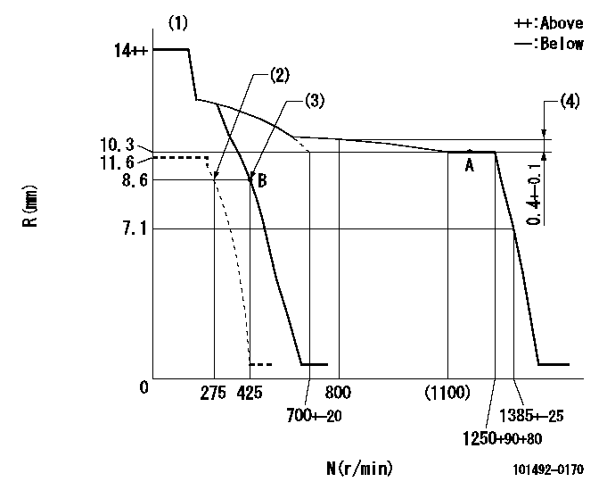
N:Pump speed
R:Rack position (mm)
(1)Target notch: K
(2)Set idle sub-spring
(3)Main spring setting
(4)Rack difference from N = N1
----------
K=7 N1=1250r/min
----------
----------
K=7 N1=1250r/min
----------
Speed control lever angle
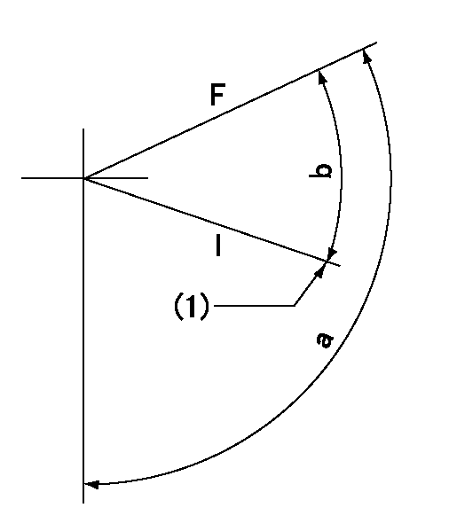
F:Full speed
I:Idle
(1)Stopper bolt setting
----------
----------
a=112deg+-5deg b=29deg+-5deg
----------
----------
a=112deg+-5deg b=29deg+-5deg
Stop lever angle
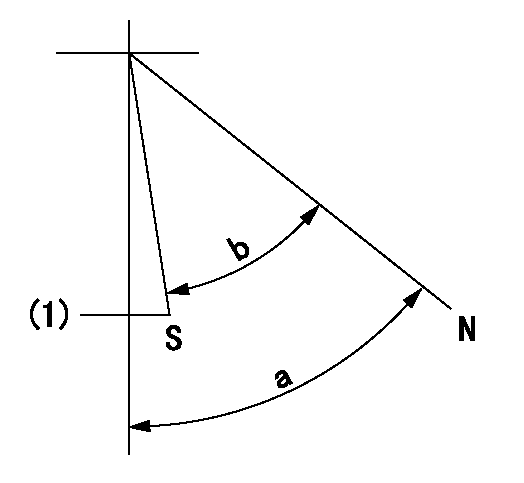
N:Pump normal
S:Stop the pump.
(1)At shipping
----------
----------
a=56.5deg+-5deg b=53deg+-5deg
----------
----------
a=56.5deg+-5deg b=53deg+-5deg
Timing setting
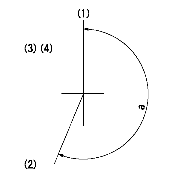
(1)Pump vertical direction
(2)Position of gear mark 'V' at No 1 cylinder's beginning of injection
(3)B.T.D.C.: aa
(4)-
----------
aa=17deg
----------
a=(200deg)
----------
aa=17deg
----------
a=(200deg)
Information:
Illustration 16 g00628694
(9) Fuel injector clamp. (10) Bolt. (11) O-ring seal.
Place the clamp (9) in the proper position. Temporarily place the jumper tube in position in order to ensure alignment of the bolt holes. Adjust the orientation of the injector until the alignment is satisfactory. Torque the bolt (10) to the following torque. Remove the jumper tube.Torque for bolt ... 47 9 N m (35 7 lb ft)
Illustration 17 g00628691
(12) O-ring seals in the injector jumper tube. (13) O-ring seals in the base of the rocker arm.
Replace the used O-ring seal (11), and the O-ring seals (12) and (13) in the jumper tube and in the rocker arm.
Illustration 18 g00628693
(14) Jumper tube. (15) Bolts. (16) Adapter. (17) Socket head screws.
Place the jumper tube (14) and the adapter (16) into position.
If the adapter was previously installed on the injector, loosen the socket head screws. Failure to loosen the socket head screws before continuing with Step 8 can result in injector failure.
Install the socket head screws (17) and the four bolts (15) finger tight.Note: The mating surfaces should be brought into complete contact and into alignment before the final torque procedure is started.
Failure to follow any of the procedures in this instruction may result in injector damage or malfunction, and possible major engine damage.
Torque Procedure
Illustration 19 g00338156
(1) Socket head screws.
Illustration 20 g00338157
(2) Two horizontal bolts. (3) Two vertical bolts.
Tighten the socket head screws (1), the two horizontal bolts (2), and the two vertical bolts (3) finger tight.
Tighten the socket head screws (1) to an initial torque of 1 .2 N m (9 2 lb in).
Tighten the horizontal bolts (2) to an initial torque of 5 3 N m (44 27 lb in).
Tighten the vertical bolts (3) to an initial torque of 5 3 N m (44 27 lb in).
Tighten the socket head screws (1) to a final torque of 12 3 N m (9 2 lb ft).
Tighten the horizontal bolts (2) to a final torque of 47 9 N m (35 7 lb ft).
Tighten the vertical bolts (3) to a final torque of 47 9 N m (35 7 lb ft).
Repeat Step 1 through Step 7 for the remainder of the injectors.
Check the fuel system for leaks by cranking the engine with the disabled injection. Then check the hydraulic pressure. Compare the pressure to the desired pressure.Cranking Without Injecting
Cranking the engine with the disabled injection may be performed by one of the following methods:
Disconnect the injector harness of the cylinders which have been reinstalled. Allow the engine to idle. Visually inspect the injector's components for high pressure oil leaks.
Activate the system "Crank Without Inject" if the option is available. On Track-Type Tractors, a "Crank Without Inject" plug can be assembled in the engine harness. On Off-Highway Trucks, the "Ground Level Shutdown" can be activated if the option is available.
When you are using the CAT ET or the ECAP, the injection may be disabled by interactive diagnostics. The engine can be left