Information injection-pump assembly
BOSCH
9 400 610 319
9400610319
ZEXEL
101492-0041
1014920041
ISUZU
5156014282
5156014282
Rating:
Service parts 101492-0041 INJECTION-PUMP ASSEMBLY:
1.
_
5.
AUTOM. ADVANCE MECHANIS
6.
COUPLING PLATE
8.
_
9.
_
11.
Nozzle and Holder
5-15300-115-1
12.
Open Pre:MPa(Kqf/cm2)
18.1{185}

15.
NOZZLE SET
Cross reference number
BOSCH
9 400 610 319
9400610319
ZEXEL
101492-0041
1014920041
ISUZU
5156014282
5156014282
Zexel num
Bosch num
Firm num
Name
9 400 610 319
5156014282 ISUZU
INJECTION-PUMP ASSEMBLY
4BC2 * K 14BC PE4A,5A, PE
4BC2 * K 14BC PE4A,5A, PE
Calibration Data:
Adjustment conditions
Test oil
1404 Test oil ISO4113 or {SAEJ967d}
1404 Test oil ISO4113 or {SAEJ967d}
Test oil temperature
degC
40
40
45
Nozzle and nozzle holder
105780-8140
Bosch type code
EF8511/9A
Nozzle
105780-0000
Bosch type code
DN12SD12T
Nozzle holder
105780-2080
Bosch type code
EF8511/9
Opening pressure
MPa
17.2
Opening pressure
kgf/cm2
175
Injection pipe
Outer diameter - inner diameter - length (mm) mm 6-2-600
Outer diameter - inner diameter - length (mm) mm 6-2-600
Tester oil delivery pressure
kPa
157
157
157
Tester oil delivery pressure
kgf/cm2
1.6
1.6
1.6
Direction of rotation (viewed from drive side)
Right R
Right R
Injection timing adjustment
Direction of rotation (viewed from drive side)
Right R
Right R
Injection order
1-3-4-2
Pre-stroke
mm
3.4
3.35
3.45
Beginning of injection position
Drive side NO.1
Drive side NO.1
Difference between angles 1
Cal 1-3 deg. 90 89.5 90.5
Cal 1-3 deg. 90 89.5 90.5
Difference between angles 2
Cal 1-4 deg. 180 179.5 180.5
Cal 1-4 deg. 180 179.5 180.5
Difference between angles 3
Cyl.1-2 deg. 270 269.5 270.5
Cyl.1-2 deg. 270 269.5 270.5
Injection quantity adjustment
Adjusting point
A
Rack position
9.9
Pump speed
r/min
900
900
900
Average injection quantity
mm3/st.
51.1
50.1
52.1
Max. variation between cylinders
%
0
-2
2
Basic
*
Fixing the lever
*
Injection quantity adjustment_02
Adjusting point
C
Rack position
9+-0.5
Pump speed
r/min
325
325
325
Average injection quantity
mm3/st.
12
10.5
13.5
Max. variation between cylinders
%
0
-14
14
Fixing the rack
*
Remarks
Adjust only variation between cylinders; adjust governor according to governor specifications.
Adjust only variation between cylinders; adjust governor according to governor specifications.
Test data Ex:
Governor adjustment
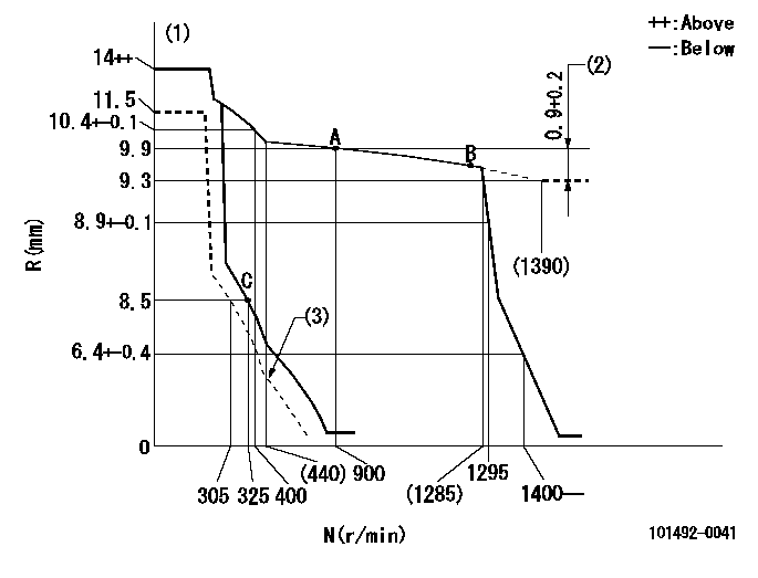
N:Pump speed
R:Rack position (mm)
(1)Target notch: K
(2)Rack difference between N = N1 and N = N2
(3)Set idle sub-spring
----------
K=12 N1=500r/min N2=1400r/min
----------
----------
K=12 N1=500r/min N2=1400r/min
----------
Speed control lever angle

F:Full speed
I:Idle
(1)Stopper bolt setting
----------
----------
a=10deg+-5deg b=24deg+-5deg
----------
----------
a=10deg+-5deg b=24deg+-5deg
Stop lever angle

N:Pump normal
S:Stop the pump.
----------
----------
a=19deg+-5deg b=53deg+-5deg
----------
----------
a=19deg+-5deg b=53deg+-5deg
Timing setting

(1)Pump vertical direction
(2)Position of gear mark 'CC' at No 1 cylinder's beginning of injection
(3)B.T.D.C.: aa
(4)-
----------
aa=18deg
----------
a=(90deg)
----------
aa=18deg
----------
a=(90deg)
Information:
1. Remove the fuel injection lines. It is not necessary to remove the fuel transfer pump, the fuel injection pump housing and governor to remove the fuel injection pumps. 2. Remove cover (1). 3. Move the rack until tool (A) can be installed to hold the rack in the center position. The rack must be in the center position to remove the fuel injection pumps.4. Use tool (B) to remove bushing (2). 5. Install tool (C) on the bonnet and remove the fuel injection pump. 6. Remove spacer (3) from the fuel injection pump housing. Spacers (3) are the same thickness for each fuel injection pump so they can be mixed. The fuel injection pump plungers and barrels are sets and can not be mixed.Install Fuel Injection Pumps
1. Install spacer (1) in the fuel injection pump housing. 2. Move the rack until tool (A) can be installed to hold the rack in the center position. The rack must be in the center position to install the fuel injection pumps.3. Turn the camshaft until the lobe of the camshaft is down for the pump to be installed. 4. Install tool (B) on the bonnet of the fuel injection pump. Put clean oil on O-ring seal (4) and install the O-ring seal and bushing (5) over tool (B) as shown. 5. Install the fuel injection pump in the pump housing with saw cut (slot) (3) in the gear in alignment with small pin (2) in the lifter assembly and groove (7) in the barrel in alignment with large pin (6) in the pump housing.6. Push down on tool (B) and tighten bushing (5) by hand until the bushing is even with the top of the housing. If installation of the bushing can not be made this far by hand, remove it. Remove the pump, put the parts in alignment again and install the bushing again.
If installation of pump is correct, the bushing can be tightened by hand until it is even with the face of the pump housing.
7. Remove tool (B) and install tool (C) in the bushing. Use tool (C) and a torque wrench to tighten the bushing to a torque of 165 14 N m (120 10 lb. ft.).8. Remove tools (C) and (A). Install the cover on the fuel injection pump housing.9. Install the fuel injection lines. Tighten the fuel injection line nuts to a torque of 41 7 N m (30 5 lb.ft.).Disassemble Fuel Injection Pumps
start by:a) remove fuel injection pumps
Be careful when the injection pumps are disassembled. Do not damage the surfaces of the plungers, barrels and bonnets. Any scratches will cause leakage inside the fuel injection pump. The plunger and barrel for each pump are made as a set. Do not put the plunger of one pump in the barrel of another pump. If one part has wear, install a complete new pump assembly. Be careful when the plunger is put into the bore of the barrel.
1. Pull plunger (1)