Information injection-pump assembly
BOSCH
F 01G 09U 02C
f01g09u02c
ZEXEL
101491-9993
1014919993
NISSAN
167000T064
167000t064
Rating:
Include in #1:
106675-4800
as _
Cross reference number
BOSCH
F 01G 09U 02C
f01g09u02c
ZEXEL
101491-9993
1014919993
NISSAN
167000T064
167000t064
Zexel num
Bosch num
Firm num
Name
Calibration Data:
Adjustment conditions
Test oil
1404 Test oil ISO4113 or {SAEJ967d}
1404 Test oil ISO4113 or {SAEJ967d}
Test oil temperature
degC
40
40
45
Nozzle and nozzle holder
105780-8140
Bosch type code
EF8511/9A
Nozzle
105780-0000
Bosch type code
DN12SD12T
Nozzle holder
105780-2080
Bosch type code
EF8511/9
Opening pressure
MPa
17.2
Opening pressure
kgf/cm2
175
Injection pipe
Outer diameter - inner diameter - length (mm) mm 6-2-600
Outer diameter - inner diameter - length (mm) mm 6-2-600
Overflow valve
131424-1520
Overflow valve opening pressure
kPa
157
123
191
Overflow valve opening pressure
kgf/cm2
1.6
1.25
1.95
Tester oil delivery pressure
kPa
157
157
157
Tester oil delivery pressure
kgf/cm2
1.6
1.6
1.6
Direction of rotation (viewed from drive side)
Right R
Right R
Injection timing adjustment
Direction of rotation (viewed from drive side)
Right R
Right R
Injection order
1-3-4-2
Pre-stroke
mm
3.2
3.15
3.25
Rack position
Point A R=A
Point A R=A
Beginning of injection position
Drive side NO.1
Drive side NO.1
Difference between angles 1
Cal 1-3 deg. 90 89.5 90.5
Cal 1-3 deg. 90 89.5 90.5
Difference between angles 2
Cal 1-4 deg. 180 179.5 180.5
Cal 1-4 deg. 180 179.5 180.5
Difference between angles 3
Cyl.1-2 deg. 270 269.5 270.5
Cyl.1-2 deg. 270 269.5 270.5
Injection quantity adjustment
Adjusting point
-
Rack position
12.7
Pump speed
r/min
1000
1000
1000
Average injection quantity
mm3/st.
74
72.4
75.6
Max. variation between cylinders
%
0
-2.5
2.5
Basic
*
Fixing the rack
*
Standard for adjustment of the maximum variation between cylinders
*
Injection quantity adjustment_02
Adjusting point
H
Rack position
9.5+-0.5
Pump speed
r/min
300
300
300
Average injection quantity
mm3/st.
9.6
7.8
11.4
Max. variation between cylinders
%
0
-15
15
Fixing the rack
*
Standard for adjustment of the maximum variation between cylinders
*
Injection quantity adjustment_03
Adjusting point
A
Rack position
R1(12.7)
Pump speed
r/min
1000
1000
1000
Average injection quantity
mm3/st.
74
73
75
Basic
*
Fixing the lever
*
Injection quantity adjustment_04
Adjusting point
B
Rack position
R1-0.2
Pump speed
r/min
1600
1600
1600
Average injection quantity
mm3/st.
80.9
76.9
84.9
Fixing the lever
*
Injection quantity adjustment_05
Adjusting point
I
Rack position
-
Pump speed
r/min
100
100
100
Average injection quantity
mm3/st.
100
84
116
Fixing the lever
*
Timer adjustment
Pump speed
r/min
990--
Advance angle
deg.
0
0
0
Remarks
Start
Start
Timer adjustment_02
Pump speed
r/min
940
Advance angle
deg.
0.3
Timer adjustment_03
Pump speed
r/min
-
Advance angle
deg.
0.8
0.5
1.1
Remarks
Measure the actual speed.
Measure the actual speed.
Timer adjustment_04
Pump speed
r/min
1345+-25
Advance angle
deg.
0.8
0.5
1.1
Timer adjustment_05
Pump speed
r/min
1600--
Advance angle
deg.
5
4.5
5.5
Remarks
Finish
Finish
Test data Ex:
Governor adjustment
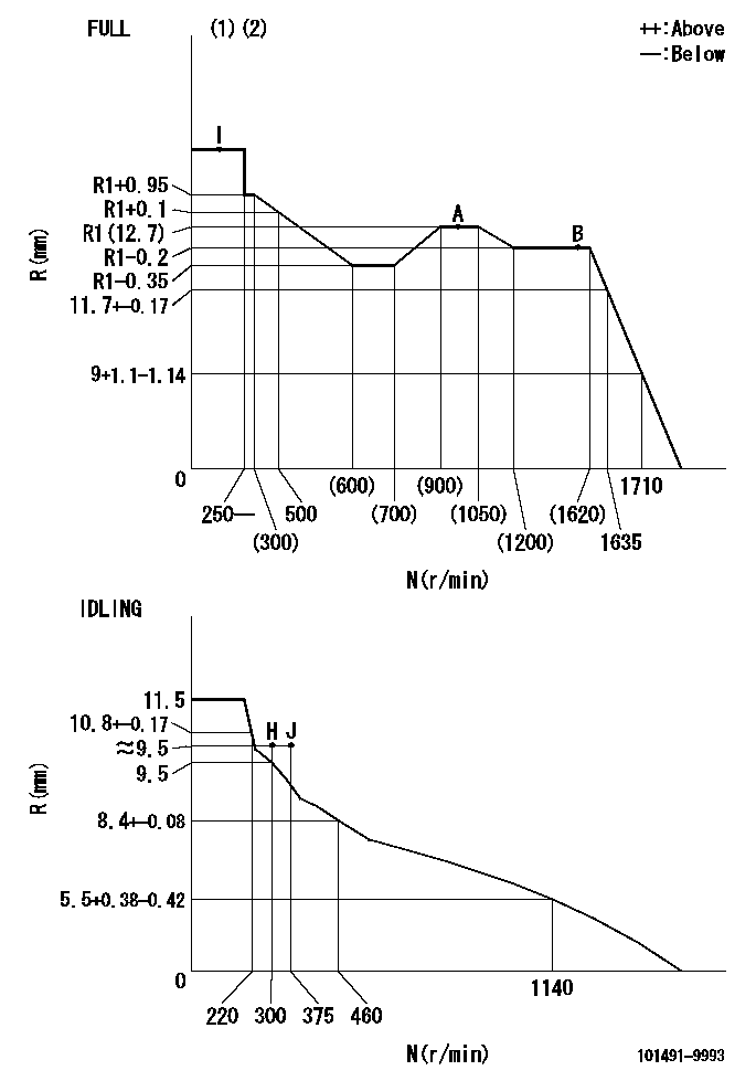
N:Pump speed
R:Rack position (mm)
(1)Torque cam stamping: T1
(2)Tolerance for racks not indicated: +-0.05mm.
----------
T1=G85
----------
----------
T1=G85
----------
Speed control lever angle
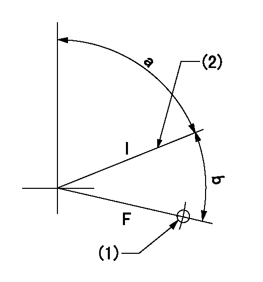
F:Full speed
I:Idle
(1)Use the hole at R = aa
(2)Stopper bolt set position 'H'
----------
aa=32mm
----------
a=70deg+-5deg b=(39deg)+-3deg
----------
aa=32mm
----------
a=70deg+-5deg b=(39deg)+-3deg
Stop lever angle

N:Pump normal
S:Stop the pump.
(1)Use the pin at R = aa
----------
aa=12mm
----------
a=29deg+-5deg b=10deg+-5deg
----------
aa=12mm
----------
a=29deg+-5deg b=10deg+-5deg
0000001501 LEVER
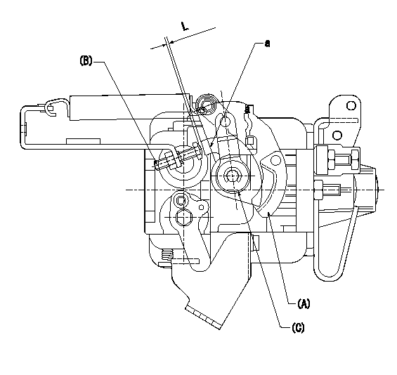
(A) Speed lever (lower)
(B) Stopper bolt
(C) Special lever (upper)
a:Point A (inside lever)
1. Special lever adjustment
(1)With the speed lever at the idle position, set the accelerator lever stopper bolt so that the accelerator lever contacts the speed lever at point a.
(2)Back off the stopper bolt L and set.
----------
L=1+0.5mm
----------
----------
L=1+0.5mm
----------
Timing setting

(1)Pump vertical direction
(2)Position of gear's standard threaded hole (position of gear mark 'S') at No 1 cylinder's beginning of injection
(3)B.T.D.C.: aa
(4)-
----------
aa=12deg
----------
a=(60deg)
----------
aa=12deg
----------
a=(60deg)
Information:
(1) Torque for the terminal nuts ... 30 3 N m (22 2 lb ft)(2) Torque for the screws that hold the nose housing to the lever housing ... 20 3 N m (15 2 lb ft)Clearance between the pinion and housing (pinion clearance) ... 8.3 to 9.9 mm (.33 to .39 in)8C3651 24V
Rotation as seen from the drive end ... clockwiseNo load conditions: Speed (rpm) ... 7350 1050Current amps ... 60 to 75Voltage ... 23Used with solenoid ... 7T02584N3180 24V, 2P3926 24V
The two 10-32 screws on the underside of the solenoid are tightened to a torque of ... 2 to 3 N m (16 to 30 lb in)Rotation as seen from the drive end ... clockwiseNo load conditions: Speed (rpm) ... 6000 to 8250Current amps ... 155 15Voltage ... 23Used with solenoid ... 3T34213T2647 24V
The two 10-32 screws on the solenoid are tightened to a torque of ... 2.25 0.25 N m (20 2 lb in)The two 1/2-13 nuts on the solenoid are tightened to a torque of ... 31 4 N m (23 3 lb ft)Rotation as seen from the drive end ... clockwiseNo load conditions: Speed (rpm) ... 8130 2130Current amps ... 89 29Voltage ... 23Used with solenoid ... 7T88543T8946 24V
Rotation as seen from the drive end ... clockwiseNo load conditions: Speed (rpm) ... 6500 1000Current amps ... 107.5 12.5Voltage ... 20Used with solenoid ... 7T88549G4338 24V
Rotation as seen from the drive end ... clockwiseMinimum (no load) speed (rpm) ... 6500Current consumption (draw) at 20V (no load) ... 77A(1) Torque for the housing bolts ... 11 N m (8 lb ft)(2) Torque for the terminal nuts ... 27 to 34 N m (20 to 25 lb ft)(3) Clearance between the pinion and housing ... 0.51 to 1.27 mm (.020 to .050 in)Used with solenoid ... 3T86353T6305 24V
Rotation as seen from the drive end ... clockwiseMaximum (no load) speed (rpm) ... 5500Maximum current consumption (draw) (no load) ... 200A(1) Torque for the large terminal nuts ... 27 to 33 N m (20 to 24 lb ft) Torque for the small terminal nuts ... 4 to 5 N m (35 to 45 lb in)(2) Service limit of brushes ... 17.5 mm (.69 in)(3) Service limit of commutater diameter ... 48 mm (1.9 in)Pinion to ring gear clearance ... 1.5 to 5.5 mm (.06 to .22 in)Used with solenoid ... 9X03329X4447 24V
(1) Torque for terminal nuts: Small terminal nuts ... 2.25 .25 N m (20 2 lb ft)Large terminal nuts ... 30.5 3.5 N m (22.5 2.5 lb ft)No load conditions: Speed (rpm) ... 3300Current amps ... 80AVoltage ... 23.5Used with solenoid ... 3E0135