Information injection-pump assembly
BOSCH
F 01G 09U 029
f01g09u029
ZEXEL
101491-9990
1014919990
NISSAN-DIESEL
167000T062
167000t062
Rating:
Cross reference number
BOSCH
F 01G 09U 029
f01g09u029
ZEXEL
101491-9990
1014919990
NISSAN-DIESEL
167000T062
167000t062
Zexel num
Bosch num
Firm num
Name
Calibration Data:
Adjustment conditions
Test oil
1404 Test oil ISO4113 or {SAEJ967d}
1404 Test oil ISO4113 or {SAEJ967d}
Test oil temperature
degC
40
40
45
Nozzle and nozzle holder
105780-8140
Bosch type code
EF8511/9A
Nozzle
105780-0000
Bosch type code
DN12SD12T
Nozzle holder
105780-2080
Bosch type code
EF8511/9
Opening pressure
MPa
17.2
Opening pressure
kgf/cm2
175
Injection pipe
Outer diameter - inner diameter - length (mm) mm 6-2-600
Outer diameter - inner diameter - length (mm) mm 6-2-600
Overflow valve
131424-1520
Overflow valve opening pressure
kPa
157
123
191
Overflow valve opening pressure
kgf/cm2
1.6
1.25
1.95
Tester oil delivery pressure
kPa
157
157
157
Tester oil delivery pressure
kgf/cm2
1.6
1.6
1.6
Direction of rotation (viewed from drive side)
Right R
Right R
Injection timing adjustment
Direction of rotation (viewed from drive side)
Right R
Right R
Injection order
1-3-4-2
Pre-stroke
mm
3.2
3.15
3.25
Rack position
Point A R=A
Point A R=A
Beginning of injection position
Drive side NO.1
Drive side NO.1
Difference between angles 1
Cal 1-3 deg. 90 89.5 90.5
Cal 1-3 deg. 90 89.5 90.5
Difference between angles 2
Cal 1-4 deg. 180 179.5 180.5
Cal 1-4 deg. 180 179.5 180.5
Difference between angles 3
Cyl.1-2 deg. 270 269.5 270.5
Cyl.1-2 deg. 270 269.5 270.5
Injection quantity adjustment
Adjusting point
-
Rack position
12.7
Pump speed
r/min
1000
1000
1000
Average injection quantity
mm3/st.
74
72.4
75.6
Max. variation between cylinders
%
0
-2.5
2.5
Basic
*
Fixing the rack
*
Standard for adjustment of the maximum variation between cylinders
*
Injection quantity adjustment_02
Adjusting point
H
Rack position
9.5+-0.5
Pump speed
r/min
300
300
300
Average injection quantity
mm3/st.
9.6
7.8
11.4
Max. variation between cylinders
%
0
-15
15
Fixing the rack
*
Standard for adjustment of the maximum variation between cylinders
*
Injection quantity adjustment_03
Adjusting point
A
Rack position
R1(12.7)
Pump speed
r/min
1000
1000
1000
Average injection quantity
mm3/st.
74
73
75
Basic
*
Fixing the lever
*
Injection quantity adjustment_04
Adjusting point
B
Rack position
R1-0.2
Pump speed
r/min
1600
1600
1600
Average injection quantity
mm3/st.
80.9
76.9
84.9
Fixing the lever
*
Injection quantity adjustment_05
Adjusting point
I
Rack position
-
Pump speed
r/min
100
100
100
Average injection quantity
mm3/st.
100
84
116
Fixing the lever
*
Timer adjustment
Pump speed
r/min
1010--
Advance angle
deg.
0
0
0
Remarks
Start
Start
Timer adjustment_02
Pump speed
r/min
960
Advance angle
deg.
0.3
Timer adjustment_03
Pump speed
r/min
(1030)
Advance angle
deg.
0.8
0.5
1.1
Remarks
Measure the actual speed.
Measure the actual speed.
Timer adjustment_04
Pump speed
r/min
-
Advance angle
deg.
0.8
0.5
1.1
Remarks
Measure the actual speed.
Measure the actual speed.
Timer adjustment_05
Pump speed
r/min
1600
Advance angle
deg.
5
4.5
5.5
Remarks
Finish
Finish
Test data Ex:
Governor adjustment
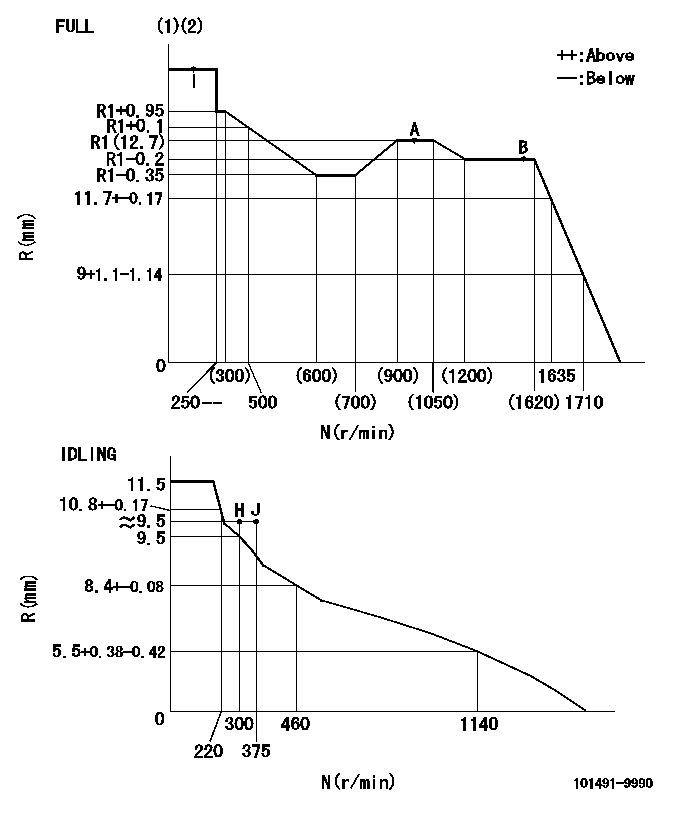
N:Pump speed
R:Rack position (mm)
(1)Torque cam stamping: T1
(2)Tolerance for racks not indicated: +-0.05mm.
----------
T1=G85
----------
----------
T1=G85
----------
Speed control lever angle
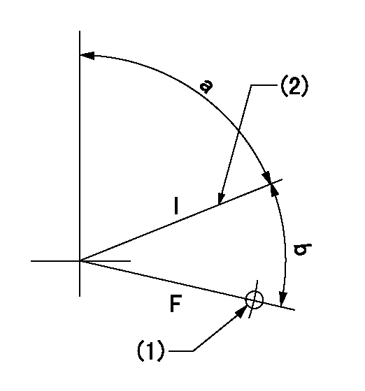
F:Full speed
I:Idle
(1)Use the hole at R = aa
(2)Stopper bolt set position 'H'
----------
aa=32mm
----------
a=70deg+-5deg b=(39deg)+-3deg
----------
aa=32mm
----------
a=70deg+-5deg b=(39deg)+-3deg
Stop lever angle

N:Pump normal
S:Stop the pump.
(1)Use the pin at R = aa
----------
aa=12mm
----------
a=29deg+-5deg b=10deg+-5deg
----------
aa=12mm
----------
a=29deg+-5deg b=10deg+-5deg
0000001501 LEVER
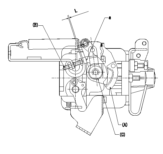
(A) Speed lever (lower)
(B) Stopper bolt
(C) Special lever (upper)
a:Point A (inside lever)
1. Special lever adjustment
(1)With the speed lever at the idle position, set the accelerator lever stopper bolt so that the accelerator lever contacts the speed lever at point a.
(2)Back off the stopper bolt L and set.
----------
L=1+0.5mm
----------
----------
L=1+0.5mm
----------
Timing setting

(1)Pump vertical direction
(2)Position of gear's standard threaded hole (position of gear mark 'S') at No 1 cylinder's beginning of injection
(3)B.T.D.C.: aa
(4)-
----------
aa=11deg
----------
a=(60deg)
----------
aa=11deg
----------
a=(60deg)
Information:
Do not bend or add stress the shaft when the nut is loosened or tightened.
d. Loosen the nut on the shaft.e. Tighten nut to ... 3.5 N m (30 lb in)f. Tighten the nut an additional ... 120°g. Remove the nut from the shaft.h. Use 6V1541 Quick Cure Primer on the threads of the shaft and nut.i. Put 9S3265 Retaining Compound on the threads of the shaft and nut.j. Again tighten the nut to ... 3.5 N m (30 lb in)k. Again tighten the nut and additional ... 120°(2) Torque for the bolts that hold back plate ... 10 1 N m (90 10 lb in)(3) Torque for the clamp bolts ... 14 1 N m (120 10 lb in)(4) Bore in the bearings ... 15.921 to 15.931 mm (.6268 to .6272 in) Diameter of the surface on the shaft for the bearings ... 15.875 to 15.885 mm (.6250 to .6254 in)(5) Bore in the housing ... 24.961 to 24.973 mm (.9827 to .9832 in) Outside diameter of the bearing ... 24.846 to 24.859 mm (.9782 to .9787 in)(6) Clearance between the ends of the oil seal ring ... 0.20 to 0.38 mm (.008 to .015 in)(7) End play for the shaft ... 0.08 to 0.25 mm (.003 to .010 in)(8) Put 5P3931 Anti-Seize Compound on the threads and tighten the bolts that hold the turbocharger to the manifold to a torque of ... 54 5 N m (40 4 lb ft)Turbocharger S4A
(1) End play for shaft (new) ... 0.114 0.038 mm (.0045 .0015 in) Maximum permissible end play (worn) ... 0.20 mm (.008 in)(2) Thickness of thrust bearing (where thrust rings contact bearing) ... 5.36 0.03 mm (.211 .001 in)(3) Tighten both band clamps with procedure that follows: a. Tighten to ... 14 1.1 N m (125 10 lb in)b. Tap (hit) clamp lightly all around.c. Tighten again to ... 14 1.1 N m (125 10 lb in)
Do not overtighten the clamps.
(4) Diameter of shaft (new) ... 15.997 to 16.005 mm (.6298 to .6301 in) Bore in the bearing (new) ... 16.035 to 16.043 mm (.6313 to .6316 in)Maximum permissible clearance between bearing and shaft (worn) ... 0.05 mm (.002 in)(5) Maximum permissible gap of oil seal ring, measured in bore of housing ... 0.25 mm (.010 in)(6) Install the compressor wheel (at room temperature) as follows: a. See Compressor Wheel Clearance for the correct shim thickness to use.b. Put compressor wheel on the shaft.c. Put a small amount of clean engine oil on the threads.d. Tighten the nut to a