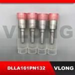
Information injection-pump assembly
BOSCH
F 019 Z10 482
f019z10482
ZEXEL
101491-9981
1014919981
NISSAN-DIESEL
167000T013
167000t013
Rating:
Service parts 101491-9981 INJECTION-PUMP ASSEMBLY:
1.
_
6.
COUPLING PLATE
7.
COUPLING PLATE
8.
_
9.
_
11.
Nozzle and Holder
166000T003
12.
Open Pre:MPa(Kqf/cm2)
18.6(190)
15.
NOZZLE SET
Cross reference number
BOSCH
F 019 Z10 482
f019z10482
ZEXEL
101491-9981
1014919981
NISSAN-DIESEL
167000T013
167000t013
Zexel num
Bosch num
Firm num
Name
Calibration Data:
Adjustment conditions
Test oil
1404 Test oil ISO4113 or {SAEJ967d}
1404 Test oil ISO4113 or {SAEJ967d}
Test oil temperature
degC
40
40
45
Nozzle and nozzle holder
105780-8140
Bosch type code
EF8511/9A
Nozzle
105780-0000
Bosch type code
DN12SD12T
Nozzle holder
105780-2080
Bosch type code
EF8511/9
Opening pressure
MPa
17.2
Opening pressure
kgf/cm2
175
Injection pipe
Outer diameter - inner diameter - length (mm) mm 6-2-600
Outer diameter - inner diameter - length (mm) mm 6-2-600
Overflow valve
131424-1520
Overflow valve opening pressure
kPa
157
123
191
Overflow valve opening pressure
kgf/cm2
1.6
1.25
1.95
Tester oil delivery pressure
kPa
157
157
157
Tester oil delivery pressure
kgf/cm2
1.6
1.6
1.6
Direction of rotation (viewed from drive side)
Right R
Right R
Injection timing adjustment
Direction of rotation (viewed from drive side)
Right R
Right R
Injection order
1-3-4-2
Pre-stroke
mm
3.2
3.15
3.25
Rack position
Point A R=A
Point A R=A
Beginning of injection position
Drive side NO.1
Drive side NO.1
Difference between angles 1
Cal 1-3 deg. 90 89.5 90.5
Cal 1-3 deg. 90 89.5 90.5
Difference between angles 2
Cal 1-4 deg. 180 179.5 180.5
Cal 1-4 deg. 180 179.5 180.5
Difference between angles 3
Cyl.1-2 deg. 270 269.5 270.5
Cyl.1-2 deg. 270 269.5 270.5
Injection quantity adjustment
Adjusting point
-
Rack position
12.7
Pump speed
r/min
1000
1000
1000
Average injection quantity
mm3/st.
74
72.4
75.6
Max. variation between cylinders
%
0
-2.5
2.5
Basic
*
Fixing the rack
*
Standard for adjustment of the maximum variation between cylinders
*
Injection quantity adjustment_02
Adjusting point
H
Rack position
9.5+-0.5
Pump speed
r/min
325
325
325
Average injection quantity
mm3/st.
10
8.2
11.8
Max. variation between cylinders
%
0
-15
15
Fixing the rack
*
Standard for adjustment of the maximum variation between cylinders
*
Injection quantity adjustment_03
Adjusting point
A
Rack position
R1(12.7)
Pump speed
r/min
1000
1000
1000
Average injection quantity
mm3/st.
74
73
75
Basic
*
Fixing the lever
*
Injection quantity adjustment_04
Adjusting point
B
Rack position
R1-0.2
Pump speed
r/min
1600
1600
1600
Average injection quantity
mm3/st.
80.9
76.9
84.9
Fixing the lever
*
Injection quantity adjustment_05
Adjusting point
I
Rack position
-
Pump speed
r/min
100
100
100
Average injection quantity
mm3/st.
100
84
116
Fixing the lever
*
Timer adjustment
Pump speed
r/min
1010--
Advance angle
deg.
0
0
0
Remarks
Start
Start
Timer adjustment_02
Pump speed
r/min
960
Advance angle
deg.
0.3
Timer adjustment_03
Pump speed
r/min
(1030)
Advance angle
deg.
0.8
0.5
1.1
Remarks
Measure the actual speed.
Measure the actual speed.
Timer adjustment_04
Pump speed
r/min
-
Advance angle
deg.
0.8
0.5
1.1
Remarks
Measure the actual speed.
Measure the actual speed.
Timer adjustment_05
Pump speed
r/min
1600
Advance angle
deg.
5
4.5
5.5
Remarks
Finish
Finish
Test data Ex:
Governor adjustment
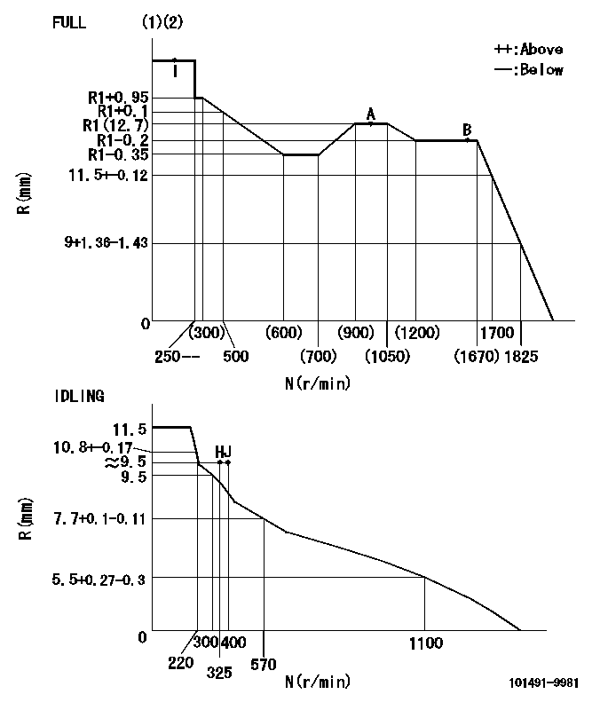
N:Pump speed
R:Rack position (mm)
(1)Torque cam stamping: T1
(2)Tolerance for racks not indicated: +-0.05mm.
----------
T1=G84
----------
----------
T1=G84
----------
Speed control lever angle
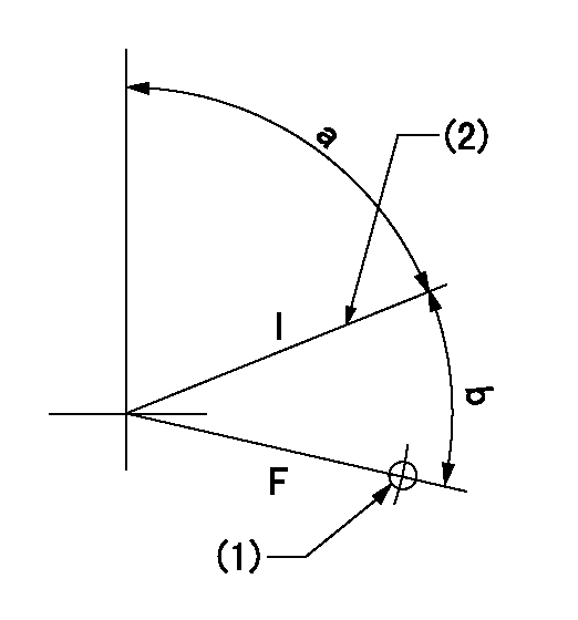
F:Full speed
I:Idle
(1)Use the hole at R = aa
(2)Stopper bolt set position 'H'
----------
aa=32mm
----------
a=71deg+-5deg b=36deg+-3deg
----------
aa=32mm
----------
a=71deg+-5deg b=36deg+-3deg
Stop lever angle

N:Pump normal
S:Stop the pump.
(1)Use the pin at R = aa
----------
aa=12mm
----------
a=29deg+-5deg b=10deg+-5deg
----------
aa=12mm
----------
a=29deg+-5deg b=10deg+-5deg
0000001501 POTENTIO METER
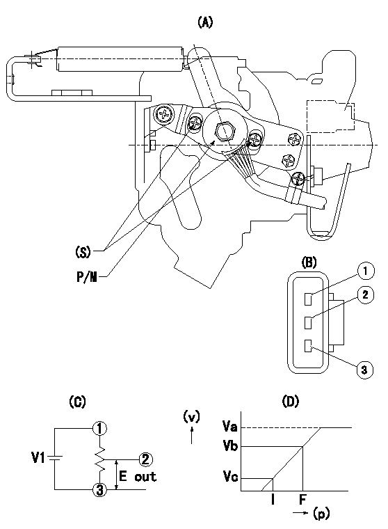
(A) : Governor plan view
(B): Potentiometer harness terminal
(C): Potentiometer connection diagram
(D) : Output voltage standard value
(S): Voltage
P/M: potentiometer
(v): output voltage (V)
(p): direction of potentiometer rotation
1. Adjustment procedures
(1)Apply DCV1 to potentiometer harness terminal (B) to obtain the specified output voltage.
(2)Fix the speed lever at the full side.
(3)Loosen the bolt (S), and move the potentiometer from left and right.
(4)Adjust so that the output voltage at full is within the standard values.
(5)Fix bolt (S).
(6)Repeatedly move the speed lever from the full side to the idle side.
(7)Check that it is within the standard values at full and idle.
----------
V1=5+-0.02V
----------
V1=5+-0.02V Va=(5)V Vb=3.65+-0.2V Vc=0.48+-0.3V
----------
V1=5+-0.02V
----------
V1=5+-0.02V Va=(5)V Vb=3.65+-0.2V Vc=0.48+-0.3V
Timing setting

(1)Pump vertical direction
(2)Position of gear's standard threaded hole (position of gear mark 'S') at No 1 cylinder's beginning of injection
(3)B.T.D.C.: aa
(4)-
----------
aa=11deg
----------
a=(60deg)
----------
aa=11deg
----------
a=(60deg)
Information:
8W0584 Wiring Group. (1) 8W7193 Harness Assembly. (2) 7T3821 Control Group. (3) 9D3721 Switch. (4) Two 7N8419 Terminals. (5) Three 4M5282 Bolts. (6) Three 5P4115 Washers.Overspeed Warning Group
All trucks with PINS 8GB1-236, a Special Instruction SEHS8863 Installation of Off-Highway Truck Engine Overspeed Warning Indicator Group was available to update these trucks with the stand alone engine overspeed system.This Special Instruction should be used for all trucks within this PIN range.* Trucks that were not retrofitted with engine overspeed.* Trucks that had been retrofitted with Special Instruction SEHS8863.Trucks That Were Not Retrofitted
Install just the items given in the following chart on these trucks. The 12 items in the chart above must be installed to complete the EUI retrofit on those trucks that had no overspeed warning installed. The following Steps were taken from Special Instruction SEHS8863. The following Steps are similar to the Steps in SEHS8863. Do only those things that are spelled out in these 12 Steps, which were taken from SEHS8863.1. Disconnect the batteries.2. Remove the cover from the front of the cab.3. Remove the instrument panel and the plastic dash. See the Service Manual for correct procedure.
As seen from inside of cab
As seen from outside of cab4. Drill hole (A) at the dimensions shown in the illustration above. 5. Cut an opening (B) in the lower part of the metal dash, to the dimensions shown with a 3.o mm (.12 in) radius at each corner. 6. Install a 8F9836 Lug (2) with a 3 mm (.12 in) fillet weld at the dimensions shown on the left side of the steering tunnel on the dash assembly. This lug will be used to mount the 9G9813 Alarm Group. 7. Drill only hole (E), 26.0 0.5 mm (1.02 .08 in) diameter, at the location shown in the illustration.8. Install the plastic dash. 9. Install 8C7535 Film (10), 3T0304 Indicator Light Base (8), 7N1996 Lamp and 6T7058 Lens in dash as shown.10. Install two 7T1874 Terminals on 3T0304 Indicator Light Base (8). 11. Install 9G9813 Alarm Group (11) with 0S0509 Bolt and 5M2894 Washer (12) as shown.12. Place the wires from the alarm group through the hole drilled in Step 4 in the dash assembly and install a 4V5091 Grommet (13).Trucks That Were Retrofitted
Remove the items installed with SEHS8863 that is given in the following chart. Throttle Pedal (8X7946 Acceleration Control Group)
(1) 1M0437 Spring. (2) 8X7985 Plate Assembly. (3) 2K8467 Pin. (4) 8T7566 Pin. (5) 8X7980 Pedal. (6) 8D7052 Spring. (7) 8X8590 Pin. (8) 8T0277 Pin. (9) 3E5400 Control Group. (10) Two 2N7456 Screw. (11) Two 4B4274 Washer. (12) 6H4006 Grommet. (13) 4D7794 Clip. (14) Three 4M0061 Bolt. (15) Three 8T4224 Washer. (16) 5H4871 Plug.1. Install 1M0437 Spring in 8X7985 Plate Assembly with 2K8467 Pin and 8T7566 Pin.2. Install 8X7980 Pedal on plate assembly with 8D7052 Spring, 8X8590 Pin and 8T0277 Spring Pin.3. Install 3E5400 Control Group to plate assembly with two 2N7456 Screws and 4B4274 Washers. 4. Insert harness through floor and place 6H4006 Grommet around hole.5.
