Information injection-pump assembly
BOSCH
9 400 614 353
9400614353
ZEXEL
101491-9870
1014919870
NISSAN-DIESEL
1671290167
1671290167

Rating:
Service parts 101491-9870 INJECTION-PUMP ASSEMBLY:
1.
_
6.
COUPLING PLATE
7.
COUPLING PLATE
8.
_
9.
_
11.
Nozzle and Holder
1660090069
12.
Open Pre:MPa(Kqf/cm2)
22.6{230}

15.
NOZZLE SET
Cross reference number
BOSCH
9 400 614 353
9400614353
ZEXEL
101491-9870
1014919870
NISSAN-DIESEL
1671290167
1671290167
Zexel num
Bosch num
Firm num
Name
101491-9870
9 400 614 353
1671290167 NISSAN-DIESEL
INJECTION-PUMP ASSEMBLY
FD33 K 14BC INJECTION PUMP ASSY PE4A,5A, PE
FD33 K 14BC INJECTION PUMP ASSY PE4A,5A, PE
Calibration Data:
Adjustment conditions
Test oil
1404 Test oil ISO4113 or {SAEJ967d}
1404 Test oil ISO4113 or {SAEJ967d}
Test oil temperature
degC
40
40
45
Nozzle and nozzle holder
105780-8140
Bosch type code
EF8511/9A
Nozzle
105780-0000
Bosch type code
DN12SD12T
Nozzle holder
105780-2080
Bosch type code
EF8511/9
Opening pressure
MPa
17.2
Opening pressure
kgf/cm2
175
Injection pipe
Outer diameter - inner diameter - length (mm) mm 6-2-600
Outer diameter - inner diameter - length (mm) mm 6-2-600
Overflow valve
131424-6120
Overflow valve opening pressure
kPa
191
157
225
Overflow valve opening pressure
kgf/cm2
1.95
1.6
2.3
Tester oil delivery pressure
kPa
157
157
157
Tester oil delivery pressure
kgf/cm2
1.6
1.6
1.6
Direction of rotation (viewed from drive side)
Right R
Right R
Injection timing adjustment
Direction of rotation (viewed from drive side)
Right R
Right R
Injection order
1-3-4-2
Pre-stroke
mm
3.4
3.35
3.45
Beginning of injection position
Drive side NO.1
Drive side NO.1
Difference between angles 1
Cal 1-3 deg. 90 89.5 90.5
Cal 1-3 deg. 90 89.5 90.5
Difference between angles 2
Cal 1-4 deg. 180 179.5 180.5
Cal 1-4 deg. 180 179.5 180.5
Difference between angles 3
Cyl.1-2 deg. 270 269.5 270.5
Cyl.1-2 deg. 270 269.5 270.5
Injection quantity adjustment
Adjusting point
A
Rack position
11.4
Pump speed
r/min
1500
1500
1500
Average injection quantity
mm3/st.
61.6
60.6
62.6
Max. variation between cylinders
%
0
-3.5
3.5
Basic
*
Fixing the lever
*
Injection quantity adjustment_02
Adjusting point
B
Rack position
9.1+-0.5
Pump speed
r/min
400
400
400
Average injection quantity
mm3/st.
8
6
10
Max. variation between cylinders
%
0
-10
10
Fixing the rack
*
Timer adjustment
Pump speed
r/min
900
Advance angle
deg.
0.5
Timer adjustment_02
Pump speed
r/min
1500
Advance angle
deg.
1.75
1.25
2.25
Timer adjustment_03
Pump speed
r/min
1800
Advance angle
deg.
3.5
3
4
Timer adjustment_04
Pump speed
r/min
-
Advance angle
deg.
4
3.5
4.5
Remarks
Measure the actual speed, stop
Measure the actual speed, stop
Test data Ex:
Governor adjustment
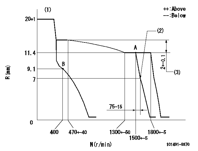
N:Pump speed
R:Rack position (mm)
(1)Target notch: K
(2)Idle sub spring setting: L1.
(3)Rack difference between N = N1 and N = N2
----------
K=12 L1=7-0.5mm N1=1500r/min N2=400r/min
----------
----------
K=12 L1=7-0.5mm N1=1500r/min N2=400r/min
----------
Speed control lever angle
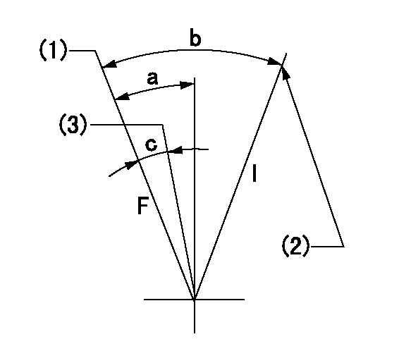
F:Full speed
I:Idle
(1)Set the pump speed at aa. ( At delivery )
(2)Stopper bolt setting
(3)Set the pump speed at bb.
----------
aa=1800r/min bb=1500r/min
----------
a=22deg+-5deg b=33deg+-5deg c=9deg+-5deg
----------
aa=1800r/min bb=1500r/min
----------
a=22deg+-5deg b=33deg+-5deg c=9deg+-5deg
Stop lever angle

N:Pump normal
S:Stop the pump.
----------
----------
a=26.5deg+-5deg b=53deg+-5deg
----------
----------
a=26.5deg+-5deg b=53deg+-5deg
0000001501 GOV FULL LOAD ADJUSTMENT
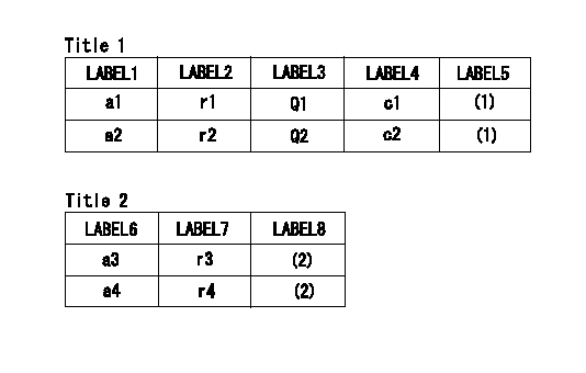
Title1:Full load stopper adjustment
Title2:Governor set speed
LABEL1:Distinguishing
LABEL2:Pump speed (r/min)
LABEL3:Ave. injection quantity (mm3/st)
LABEL4:Max. var. bet. cyl.
LABEL5:Remarks
LABEL6:Distinguishing
LABEL7:Governor set speed (r/min)
LABEL8:Remarks
(1)Adjustment conditions are the same as those for measuring injection quantity.
(2)-
----------
----------
a1=A a2=- r1=1500r/min r2=- Q1=61.6+-1mm3/st Q2=- c1=+-3.5% c2=- a3=36 a4=35 r3=1800r/min r4=1500r/min
----------
----------
a1=A a2=- r1=1500r/min r2=- Q1=61.6+-1mm3/st Q2=- c1=+-3.5% c2=- a3=36 a4=35 r3=1800r/min r4=1500r/min
Timing setting

(1)Pump vertical direction
(2)Position of gear's standard threaded hole (position of gear mark 'T') at No 1 cylinder's beginning of injection
(3)B.T.D.C.: aa
(4)-
----------
aa=19deg
----------
a=(60deg)
----------
aa=19deg
----------
a=(60deg)
Information:
6N9294 Alternator Group, 3T6352 Alternator 24V 35A (Delco-Remy Number 1117647)
Load the battery with a carbon pile (6V4930 Battery Load Tester) to get the maximum alternator output.Polarity ... Negative GroundRotation ... Either DirectionSpeed for testing (rpm) ... 5000Output voltage ... 27.5 1.0VOutput (hot) ... 35A(1) Torque for the ground terminal nut ... 2.3 0.6 N m (21 5 lb in)(2) Torque for the pulley nut ... 102 7 N m (76 5 lb ft)(3) Torque for the output terminal nut ... 7.1 0.9 N m (64 8 lb in)3T6354 Regulator (Delco-Remy Number 1116405) Inside Alternator
Voltage setting ... No adjustmentPermissible voltage range ... 26 to 30VDelco-Remy (25SI)
5S9088 Alternator Group, 3T1888 Alternator 24V 50A (Delco-Remy Number 1117248)
Load the battery with a carbon pile (6V4930 Battery Load Tester) to get the maximum alternator output.Polarity ... Negative GroundRotation ... Either DirectionSpeed for testing (rpm) ... 5000Output (hot) ... 50A(1) Torque for the pulley nut ... 102 7 N m (76 5 lb ft)(2) Torque for the output terminal nut ... 13.5 1.3 N m (10 1 lb ft)7N129 Regulator (Delco-Remy Number 1892824) Inside Alternator
Voltage setting range ... 27.5 1.0VAdjust voltage setting to ... 28V There are two types of adjustment: One type of adjustment is made by removing a pipe plug and turning the adjusting screw one or two notches in a clockwise direction to increase the voltage setting or one or two notches in a counterclockwise direction to decrease the voltage setting. The second type of adjustment is similar except, remove the end cover to expose the potentiometer for adjustment.Then increase speed to get a maximum output of ... 50ABosch
6N9294 Alternator Group, 7N9720 Alternator 24V 35A (Bosch Number 0-122-469-001)
Load the battery with a carbon pile (6V4930 Battery Load Tester) to get the maximum alternator output.Polarity ... Negative GroundRotation ... Either DirectionSpeed for testing (rpm) ... 5000Output voltage ... 27.5 1.0VOutput (hot) ... 37ATorque for the ground terminal nut ... 2.1 to 2.8 N m (19 to 25 lb in)(1) Torque for the pulley nut ... 95 to 110 N m (70 to 80 lb ft)(2) Torque for the output terminal nut ... 13.5 1.3 N m (10 1 lb ft)9G7567 Regulator (Bosch Number 1-197-011-000) Under Alternator Cover. For
Have questions with 101491-9870?
Group cross 101491-9870 ZEXEL
Nissan-Diesel
Mazda
Mazda
Mazda
Nissan-Diesel
Mazda
Nissan-Diesel
101491-9870
9 400 614 353
1671290167
INJECTION-PUMP ASSEMBLY
FD33
FD33