Information injection-pump assembly
ZEXEL
101491-9830
1014919830
Rating:
Service parts 101491-9830 INJECTION-PUMP ASSEMBLY:
1.
_
6.
COUPLING PLATE
7.
COUPLING PLATE
8.
_
9.
_
11.
Nozzle and Holder
SL70 13 H50A
12.
Open Pre:MPa(Kqf/cm2)
16.7{170}

15.
NOZZLE SET
Cross reference number
ZEXEL
101491-9830
1014919830
Zexel num
Bosch num
Firm num
Name
101491-9830
INJECTION-PUMP ASSEMBLY
14BC PE4A,5A, PE
14BC PE4A,5A, PE
Calibration Data:
Adjustment conditions
Test oil
1404 Test oil ISO4113 or {SAEJ967d}
1404 Test oil ISO4113 or {SAEJ967d}
Test oil temperature
degC
40
40
45
Nozzle and nozzle holder
105780-8140
Bosch type code
EF8511/9A
Nozzle
105780-0000
Bosch type code
DN12SD12T
Nozzle holder
105780-2080
Bosch type code
EF8511/9
Opening pressure
MPa
17.2
Opening pressure
kgf/cm2
175
Injection pipe
Outer diameter - inner diameter - length (mm) mm 6-2-600
Outer diameter - inner diameter - length (mm) mm 6-2-600
Overflow valve opening pressure
kPa
157
123
191
Overflow valve opening pressure
kgf/cm2
1.6
1.25
1.95
Tester oil delivery pressure
kPa
157
157
157
Tester oil delivery pressure
kgf/cm2
1.6
1.6
1.6
Direction of rotation (viewed from drive side)
Right R
Right R
Injection timing adjustment
Direction of rotation (viewed from drive side)
Right R
Right R
Injection order
1-3-4-2
Pre-stroke
mm
3.4
3.35
3.45
Beginning of injection position
Drive side NO.1
Drive side NO.1
Difference between angles 1
Cal 1-3 deg. 90 89.5 90.5
Cal 1-3 deg. 90 89.5 90.5
Difference between angles 2
Cal 1-4 deg. 180 179.5 180.5
Cal 1-4 deg. 180 179.5 180.5
Difference between angles 3
Cyl.1-2 deg. 270 269.5 270.5
Cyl.1-2 deg. 270 269.5 270.5
Injection quantity adjustment
Adjusting point
-
Rack position
10.9
Pump speed
r/min
1000
1000
1000
Average injection quantity
mm3/st.
49.4
48.9
49.9
Max. variation between cylinders
%
0
-2.5
2.5
Basic
*
Fixing the rack
*
Standard for adjustment of the maximum variation between cylinders
*
Injection quantity adjustment_02
Adjusting point
-
Rack position
9.6+-0.5
Pump speed
r/min
325
325
325
Average injection quantity
mm3/st.
9
7
11
Max. variation between cylinders
%
0
-14
14
Fixing the rack
*
Standard for adjustment of the maximum variation between cylinders
*
Remarks
Adjust only variation between cylinders; adjust governor according to governor specifications.
Adjust only variation between cylinders; adjust governor according to governor specifications.
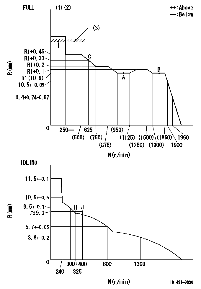
Injection quantity adjustment_03
Adjusting point
A
Rack position
R1(10.9)
Pump speed
r/min
1000
1000
1000
Average injection quantity
mm3/st.
49.4
48.9
49.9
Basic
*
Fixing the lever
*
Injection quantity adjustment_04
Adjusting point
B
Rack position
R1(10.9)
Pump speed
r/min
1700
1700
1700
Average injection quantity
mm3/st.
55.2
51.2
59.2
Fixing the lever
*
Injection quantity adjustment_05
Adjusting point
C
Rack position
R1+0.33
Pump speed
r/min
625
625
625
Average injection quantity
mm3/st.
39.8
35.8
43.8
Fixing the lever
*
Injection quantity adjustment_06
Adjusting point
I
Rack position
-
Pump speed
r/min
100
100
100
Average injection quantity
mm3/st.
91
81
96
Fixing the lever
*
Rack limit
*
Injection quantity adjustment_07
Adjusting point
H
Rack position
9.3+-0.5
Pump speed
r/min
325
325
325
Average injection quantity
mm3/st.
7
6.5
7.5
Fixing the lever
*
Timer adjustment
Pump speed
r/min
1330+-25
Advance angle
deg.
0
0
0
Remarks
Start
Start
Timer adjustment_02
Pump speed
r/min
1700
Advance angle
deg.
3.5
3.2
3.8
Remarks
Finish
Finish
Test data Ex:
Governor adjustment
N:Pump speed
R:Rack position (mm)
(1)Torque cam stamping: T1
(2)Tolerance for racks not indicated: +-0.05mm.
(3)RACK LIMIT
----------
T1=G05
----------
----------
T1=G05
----------
Speed control lever angle

F:Full speed
I:Idle
(1)Stopper bolt set position 'H' (rack position = aa, speed = bb)
----------
aa=(9.3)mm bb=325r/min
----------
a=20deg+-5deg b=(41deg)+-3deg
----------
aa=(9.3)mm bb=325r/min
----------
a=20deg+-5deg b=(41deg)+-3deg
Stop lever angle
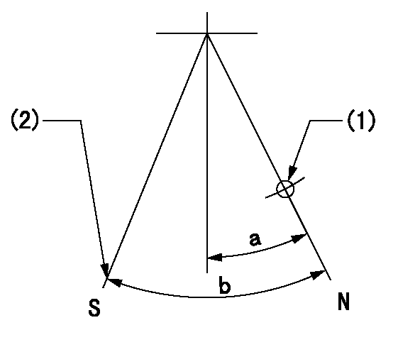
N:Pump normal
S:Engine stop
(1)Use the hole at R = aa
(2)Set the stop adjuster screw
----------
aa=39mm
----------
a=14deg+-5deg b=(30deg)+-5deg
----------
aa=39mm
----------
a=14deg+-5deg b=(30deg)+-5deg
0000001501 LEVER
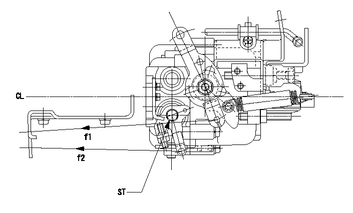
CL:Center line of camshaft
ST:Stop adjuster screw
f1:Direction for pulling the speed lever
f2:Direction for pulling the stop lever
1. Stop lever adjustment outline
(1)After completing all adjustments, confirm that the lever angle is within the specifications in the normal position.
(2)Set the speed lever in the full speed position.
(3)At pump speed Na, position the rack at non-injection position Ra.
(4)Set the stop adjusting screw to fix the speed lever in the idling position.
(5)Confirm that there is no injection at pump speed Nb.
----------
Na=1860r/min Nb=325r/min Ra=4.6+-0.3mm
----------
----------
Na=1860r/min Nb=325r/min Ra=4.6+-0.3mm
----------
0000001601 ACS

(A) Set screw
(B) Push rod 1
(C) Push rod 2
(D) Cover
1. Aneroid compensator unit adjustment
(1)Select the push rod 2 to obtain L2.
(2)Screw in (A) to obtain L1.
2. Adjustment when mounting the governor.
(1)Set the speed of the pump to N1 r/min and fix the control lever at the full set position.
(2)Screw in the aneroid compensator to obtain the performance shown in the graph above.
(3)As there is hysterisis, measure when the absolute pressure drops.
(4)Hysterisis must not exceed rack position = h1.
----------
N1=1000r/min L1=(1.5)mm L2=11+-0.5mm h1=-
----------
Ra=R1(10.9)mm Rb=(R1-0.41)mm Pa=88.6+-2.7kPa(665+-20mmHg) Pb=79.4+-0.7kPa(596+-5mmHg) Q1=49.4+-0.5cm3/1000st Q2=42.5+-1cm3/1000st
----------
N1=1000r/min L1=(1.5)mm L2=11+-0.5mm h1=-
----------
Ra=R1(10.9)mm Rb=(R1-0.41)mm Pa=88.6+-2.7kPa(665+-20mmHg) Pb=79.4+-0.7kPa(596+-5mmHg) Q1=49.4+-0.5cm3/1000st Q2=42.5+-1cm3/1000st
Timing setting

(1)Pump vertical direction
(2)Position of gear mark 'CC' at No 1 cylinder's beginning of injection
(3)B.T.D.C.: aa
(4)-
----------
aa=13deg
----------
a=(130deg)
----------
aa=13deg
----------
a=(130deg)
Information:
You must read and understand the warnings and instructions contained in the Safety section of this manual, before performing any operation or maintenance procedures.Cooling System
Do not perform this maintenance until you read and understand the material in the Safety and Cooling System Specifications sections of this publication.
Drain/Flush/Replace Coolant (Long Life Coolant/Antifreeze Only)
Caterpillar Long Life Coolant/Antifreeze should be replaced every 6,000 Service Hours or 4 Years, whichever comes first. Only clean water is needed to clean and flush the cooling system when LLCA is drained and replaced.Drain
1. Stop the engine and allow the engine to cool. Loosen the coolant filler cap slowly to relieve any pressure, and remove the cap.2. Remove the radiator drain plug, or open the radiator drain valve (if equipped). Remove the block and oil cooler drain plugs. Remove the drain plug from the bottom of the water pump housing. Allow the coolant to drain.
Dispose of used engine coolant properly or recycle. Various methods have been proposed to reclaim used coolant for reuse in engine cooling systems. The full distillation procedure is the only method acceptable by Caterpillar to reclaim the used coolant. Contact your Caterpillar for information regarding disposal and recycling of used coolant.
For information regarding disposal and recycling of used coolant:Contact Caterpillar Service Technology Group:Outside Illinois: 1-800-542-TOOLInside Illinois: 1-800-541-TOOLCanada: 1-800-523-TOOLFlush
4. Flush the cooling system with clean water to remove any debris.5. Clean and install all drain plugs and/or close the drain valve(s).6. Fill the cooling system with clean water. Install the filler cap. Operate the engine until warm 49 to 66°C (150 to 120°F).7. Stop the engine and allow the engine to cool. Loosen the coolant filler cap slowly to relieve any pressure, and remove the cap. Remove the cooling system drain plug(s) or open the drain valve. Allow the water to drain. Flush the cooling system with clean water.8. Repeat steps 6 and 7.Fill
9. Fill the cooling system with LLCA. Refer to the refill capacities chart in this manual for the amount of LLCA needed to refill your system.10. Start and run the engine with the filler cap removed. Allow the LLCA to warm, the thermostat to open, and the coolant level to stabilize. Add LLCA if necessary to bring the coolant to the proper level.11. Check the condition of the filler cap gasket. If the gasket is damaged, discard the old filler cap and install a new filler cap. If the gasket is not damaged, use a 9S8140 Service Tool (available from your Caterpillar dealer) to pressure test the filler cap. The correct filler cap pressure is stamped on the face of the filler cap. If the filler cap does not hold the correct pressure, install a new filler cap.12. Start the engine and inspect for coolant leaks and proper operating temperature.
Have questions with 101491-9830?
Group cross 101491-9830 ZEXEL
Nissan-Diesel
Mazda
Mazda
101491-9830
INJECTION-PUMP ASSEMBLY