Information injection-pump assembly
ZEXEL
101491-9800
1014919800
Rating:
Cross reference number
ZEXEL
101491-9800
1014919800
Zexel num
Bosch num
Firm num
Name
101491-9800
INJECTION-PUMP ASSEMBLY
Calibration Data:
Adjustment conditions
Test oil
1404 Test oil ISO4113 or {SAEJ967d}
1404 Test oil ISO4113 or {SAEJ967d}
Test oil temperature
degC
40
40
45
Nozzle and nozzle holder
105780-8140
Bosch type code
EF8511/9A
Nozzle
105780-0000
Bosch type code
DN12SD12T
Nozzle holder
105780-2080
Bosch type code
EF8511/9
Opening pressure
MPa
17.2
Opening pressure
kgf/cm2
175
Injection pipe
Outer diameter - inner diameter - length (mm) mm 6-2-600
Outer diameter - inner diameter - length (mm) mm 6-2-600
Overflow valve
132424-0620
Overflow valve opening pressure
kPa
157
123
191
Overflow valve opening pressure
kgf/cm2
1.6
1.25
1.95
Tester oil delivery pressure
kPa
157
157
157
Tester oil delivery pressure
kgf/cm2
1.6
1.6
1.6
Direction of rotation (viewed from drive side)
Right R
Right R
Injection timing adjustment
Direction of rotation (viewed from drive side)
Right R
Right R
Injection order
1-3-4-2
Pre-stroke
mm
3.2
3.15
3.25
Rack position
Point A R=A
Point A R=A
Beginning of injection position
Drive side NO.1
Drive side NO.1
Difference between angles 1
Cal 1-3 deg. 90 89.5 90.5
Cal 1-3 deg. 90 89.5 90.5
Difference between angles 2
Cal 1-4 deg. 180 179.5 180.5
Cal 1-4 deg. 180 179.5 180.5
Difference between angles 3
Cyl.1-2 deg. 270 269.5 270.5
Cyl.1-2 deg. 270 269.5 270.5
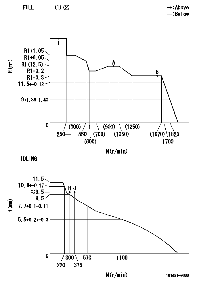
Injection quantity adjustment
Adjusting point
-
Rack position
12.5
Pump speed
r/min
950
950
950
Average injection quantity
mm3/st.
72.1
70.5
73.7
Max. variation between cylinders
%
0
-2.5
2.5
Basic
*
Fixing the rack
*
Standard for adjustment of the maximum variation between cylinders
*
Injection quantity adjustment_02
Adjusting point
H
Rack position
9.5+-0.5
Pump speed
r/min
300
300
300
Average injection quantity
mm3/st.
10
8.2
11.8
Max. variation between cylinders
%
0
-15
15
Fixing the rack
*
Standard for adjustment of the maximum variation between cylinders
*
Injection quantity adjustment_03
Adjusting point
A
Rack position
R1(12.5)
Pump speed
r/min
950
950
950
Average injection quantity
mm3/st.
72.1
71.1
73.1
Basic
*
Fixing the lever
*
Injection quantity adjustment_04
Adjusting point
B
Rack position
R1-0.3
Pump speed
r/min
1600
1600
1600
Average injection quantity
mm3/st.
79.7
75.7
83.7
Fixing the lever
*
Injection quantity adjustment_05
Adjusting point
I
Rack position
-
Pump speed
r/min
100
100
100
Average injection quantity
mm3/st.
89
73
105
Fixing the lever
*
Timer adjustment
Pump speed
r/min
1000--
Advance angle
deg.
0
0
0
Remarks
Start
Start
Timer adjustment_02
Pump speed
r/min
950
Advance angle
deg.
0.5
Timer adjustment_03
Pump speed
r/min
(1000)
Advance angle
deg.
1
0.5
1.5
Remarks
Measure the actual speed.
Measure the actual speed.
Timer adjustment_04
Pump speed
r/min
1275+50
Advance angle
deg.
1
0.5
1.5
Timer adjustment_05
Pump speed
r/min
1580
Advance angle
deg.
4.5
4
5
Remarks
Finish
Finish
Test data Ex:
Governor adjustment
N:Pump speed
R:Rack position (mm)
(1)Torque cam stamping: T1
(2)Tolerance for racks not indicated: +-0.05mm.
----------
T1=F97
----------
----------
T1=F97
----------
Speed control lever angle
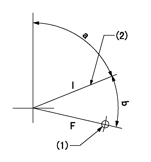
F:Full speed
I:Idle
(1)Use the hole at R = aa
(2)Stopper bolt set position 'H'
----------
aa=32mm
----------
a=70deg+-5deg b=37deg+-3deg
----------
aa=32mm
----------
a=70deg+-5deg b=37deg+-3deg
Stop lever angle

N:Pump normal
S:Stop the pump.
(1)Use the pin at R = aa
----------
aa=12mm
----------
a=29deg+-5deg b=10deg+-5deg
----------
aa=12mm
----------
a=29deg+-5deg b=10deg+-5deg
0000001501 POTENTIO METER
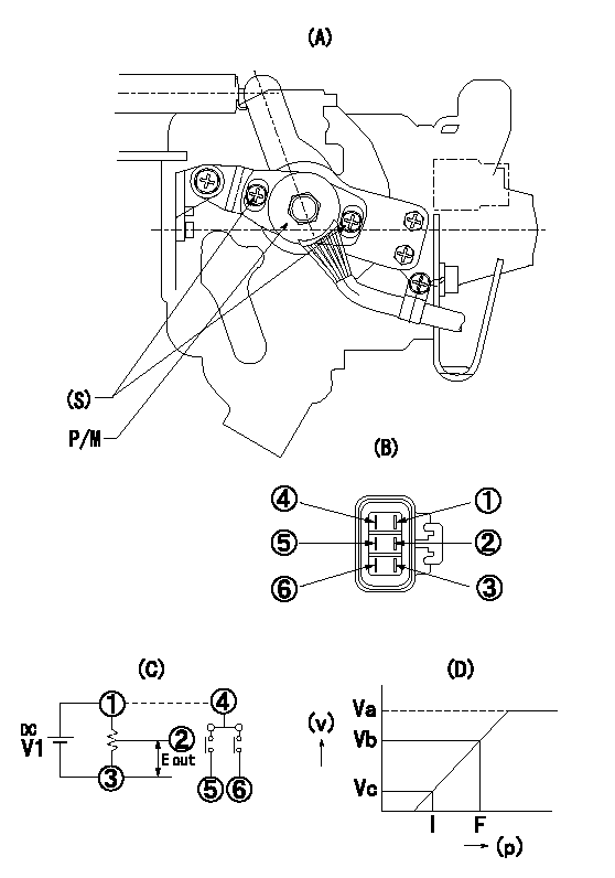
(A) : Governor plan view
(B): Potentiometer harness terminal
(C): Potentiometer connection diagram
(D) : Output voltage standard value
(S): Voltage
P/M: potentiometer
(v): output voltage (V)
(p): direction of potentiometer rotation
1. Adjustment procedures
(1)Apply DCV1 to potentiometer harness terminal (B) to obtain the specified output voltage.
(2)Fix the speed lever at the full side.
(3)Loosen the bolt (S), and move the potentiometer from left and right.
(4)Adjust so that the output voltage at full is within the standard values.
(5)Fix bolt (S).
(6)Repeatedly move the speed lever from the full side to the idle side.
(7)Check that it is within the standard values at full and idle.
----------
V1=5+-0.02V
----------
V1=5+-0.02V Va=(5)V Vb=3.71+-0.2V Vc=0.54+-0.3V
----------
V1=5+-0.02V
----------
V1=5+-0.02V Va=(5)V Vb=3.71+-0.2V Vc=0.54+-0.3V
Timing setting

(1)Pump vertical direction
(2)Position of gear's standard threaded hole (position of gear mark 'S') at No 1 cylinder's beginning of injection
(3)B.T.D.C.: aa
(4)-
----------
aa=11deg
----------
a=(60deg)
----------
aa=11deg
----------
a=(60deg)
Information:
Caterpillar's Scheduled Oil Sampling (S*O*S) analysis is the best indicator for determining what is happening inside your engine.S*O*S analysis is a diagnostic tool used to determine oil performance and component wear rates. S*O*S analysis uses a series of tests designed to identify and measure contamination such as:* soot, sulfur, etc.* degradation such as the presence of fuel, water and antifreeze in a sample of oil.* the amount of wear metals present in the oil sample.Wear metal present in the oil sample are compared to established Caterpillar norms to determine acceptability. S*O*S analysis must be performed on a continuing basis to be effective as an indicator. Intermittent sampling does not allow wear rate trend lines to be established.Obtain S*O*S samples at regularly scheduled intervals to monitor the condition and maintenance requirement of your engine. Each oil sample should be taken when the oil is warm and well mixed to ensure that the sample is representative of the oil in the engine crankcase.Consult your Caterpillar dealer for complete information and assistance in establishing an S*O*S analysis program for your engine(s).S*O*S Analysis
S*O*S analysis is composed of three basic tests:* Wear analysis* Chemical and Physical Tests* Oil Condition Analysis Wear analysis is performed with an atomic absorption spectrophotometer to monitor component wear by identifying and measuring concentrations, in parts per million, of wear elements present in the oil. Based on known normal concentrations data, maximum limits of wear elements are established. Impending failures can be identified when test results deviate form concentration levels established as acceptable, based on normal wear. Chemical and Physical Tests detect the presence of water, fuel and glycol (antifreeze) in the oil and determine whether or not their concentrations exceed established maximum limits. Oil Condition is evaluated with infrared analysis. This determines the presence and measures the amount of contaminants such as soot, sulfur products, oxidation, and nitration products in the oil. Infrared analysis can also assist in customizing (reducing, maintaining or extending) oil change intervals for particular conditions and applications.Infrared analysis should always be accompanied by wear element analysis and chemical and physical test to assure accurate diagnosis. Infrared analysis must be used to determine oil change intervals. S*O*S analysis must include Infrared (IR) in the analysis.The test results of the oil samples will then be used as a basis for determining the oil change interval for your engine, giving you the ultimate time between oil changes without the risk of engine damage.Refer to Caterpillar pamphlet Listen To Your Oil (PEDP1129) for information and benefits of S*O*S analysis.
S*O*S analysis is composed of three basic tests:* Wear analysis* Chemical and Physical Tests* Oil Condition Analysis Wear analysis is performed with an atomic absorption spectrophotometer to monitor component wear by identifying and measuring concentrations, in parts per million, of wear elements present in the oil. Based on known normal concentrations data, maximum limits of wear elements are established. Impending failures can be identified when test results deviate form concentration levels established as acceptable, based on normal wear. Chemical and Physical Tests detect the presence of water, fuel and glycol (antifreeze) in the oil and determine whether or not their concentrations exceed established maximum limits. Oil Condition is evaluated with infrared analysis. This determines the presence and measures the amount of contaminants such as soot, sulfur products, oxidation, and nitration products in the oil. Infrared analysis can also assist in customizing (reducing, maintaining or extending) oil change intervals for particular conditions and applications.Infrared analysis should always be accompanied by wear element analysis and chemical and physical test to assure accurate diagnosis. Infrared analysis must be used to determine oil change intervals. S*O*S analysis must include Infrared (IR) in the analysis.The test results of the oil samples will then be used as a basis for determining the oil change interval for your engine, giving you the ultimate time between oil changes without the risk of engine damage.Refer to Caterpillar pamphlet Listen To Your Oil (PEDP1129) for information and benefits of S*O*S analysis.
Have questions with 101491-9800?
Group cross 101491-9800 ZEXEL
101491-9800
INJECTION-PUMP ASSEMBLY