Information injection-pump assembly
BOSCH
9 400 614 350
9400614350
ZEXEL
101491-9782
1014919782
HYUNDAI
3310041C01
3310041c01
Rating:
Service parts 101491-9782 INJECTION-PUMP ASSEMBLY:
1.
_
6.
COUPLING PLATE
7.
COUPLING PLATE
8.
_
9.
_
11.
Nozzle and Holder
12.
Open Pre:MPa(Kqf/cm2)
17.7{180}

15.
NOZZLE SET
Cross reference number
BOSCH
9 400 614 350
9400614350
ZEXEL
101491-9782
1014919782
HYUNDAI
3310041C01
3310041c01
Zexel num
Bosch num
Firm num
Name
101491-9782
9 400 614 350
3310041C01 HYUNDAI
INJECTION-PUMP ASSEMBLY
4D31 * K
4D31 * K
Calibration Data:
Adjustment conditions
Test oil
1404 Test oil ISO4113 or {SAEJ967d}
1404 Test oil ISO4113 or {SAEJ967d}
Test oil temperature
degC
40
40
45
Nozzle and nozzle holder
105780-8140
Bosch type code
EF8511/9A
Nozzle
105780-0000
Bosch type code
DN12SD12T
Nozzle holder
105780-2080
Bosch type code
EF8511/9
Opening pressure
MPa
17.2
Opening pressure
kgf/cm2
175
Injection pipe
Outer diameter - inner diameter - length (mm) mm 6-2-600
Outer diameter - inner diameter - length (mm) mm 6-2-600
Overflow valve
131424-6220
Overflow valve opening pressure
kPa
255
221
289
Overflow valve opening pressure
kgf/cm2
2.6
2.25
2.95
Tester oil delivery pressure
kPa
157
157
157
Tester oil delivery pressure
kgf/cm2
1.6
1.6
1.6
Direction of rotation (viewed from drive side)
Right R
Right R
Injection timing adjustment
Direction of rotation (viewed from drive side)
Right R
Right R
Injection order
1-3-4-2
Pre-stroke
mm
3.6
3.55
3.65
Beginning of injection position
Drive side NO.1
Drive side NO.1
Difference between angles 1
Cal 1-3 deg. 90 89.5 90.5
Cal 1-3 deg. 90 89.5 90.5
Difference between angles 2
Cal 1-4 deg. 180 179.5 180.5
Cal 1-4 deg. 180 179.5 180.5
Difference between angles 3
Cyl.1-2 deg. 270 269.5 270.5
Cyl.1-2 deg. 270 269.5 270.5
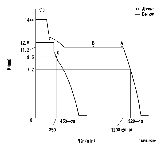
Injection quantity adjustment
Adjusting point
A
Rack position
11.2
Pump speed
r/min
1200
1200
1200
Average injection quantity
mm3/st.
38.3
37.3
39.3
Max. variation between cylinders
%
0
-2.5
2.5
Basic
*
Fixing the lever
*
Injection quantity adjustment_02
Adjusting point
-
Rack position
10.5+-0.
5
Pump speed
r/min
350
350
350
Average injection quantity
mm3/st.
9.6
8.6
10.6
Max. variation between cylinders
%
0
-15
15
Fixing the rack
*
Remarks
Adjust only variation between cylinders; adjust governor according to governor specifications.
Adjust only variation between cylinders; adjust governor according to governor specifications.
Timer adjustment
Pump speed
r/min
1200++
Advance angle
deg.
0
0
0
Remarks
Do not advance until starting N = 1200.
Do not advance until starting N = 1200.
Timer adjustment_02
Pump speed
r/min
1200
Advance angle
deg.
0.5
Timer adjustment_03
Pump speed
r/min
-
Advance angle
deg.
3
3
3
Remarks
Measure the actual speed, stop
Measure the actual speed, stop
Test data Ex:
Governor adjustment
N:Pump speed
R:Rack position (mm)
(1)Target notch: K
----------
K=9
----------
----------
K=9
----------
Speed control lever angle
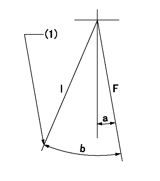
F:Full speed
I:Idle
(1)Stopper bolt setting
----------
----------
a=5deg+-5deg b=27deg+-5deg
----------
----------
a=5deg+-5deg b=27deg+-5deg
Stop lever angle

N:Pump normal
S:Stop the pump.
----------
----------
a=27deg+-5deg b=53deg+-5deg
----------
----------
a=27deg+-5deg b=53deg+-5deg
Timing setting

(1)Pump vertical direction
(2)Position of gear mark '3' at No 1 cylinder's beginning of injection
(3)B.T.D.C.: aa
(4)-
----------
aa=12deg
----------
a=(130deg)
----------
aa=12deg
----------
a=(130deg)
Information:
Stopping the engine immediately after it has been working under load can result in overheating and accelerated wear of the engine components. Allow the engine to cool down before stopping. Avoiding hot engine shutdowns will maximize turbocharger shaft and bearing life.
Emergency Stopping
Emergency shutoff controls are for EMERGENCY use ONLY. DO NOT use Emergency shutoff devices or controls for normal stopping procedure.
Make sure that any external system components that have been operating to support engine operation are secured after any stop.Emergency Stop Buttons
Emergency Stop Button, shown mounted on a junction box.Emergency stops may be made by pushing the Emergency Stop Button located on the junction box (if equipped). Both the Button and the air inlet shutoff (if equipped) require resetting before the engine will start.
Control Panel Emergency Stop Button.If equipped with the EMCPII Control Panel, press the Emergency Stop Button for an emergency stop. The ECS must be reset before resuming operation. Move the ECS to the OFF/RESET position. The ECS can also be used to shut the engine off in an emergency. Move the ECS to the OFF/RESET position. The engine will immediately shut off.Manual Stopping
A manual shutoff shaft is provided to override the governor control. The shaft will move the fuel control linkage to the FUEL OFF position. Refer to the Model Views for the engine location of the shaft. The engine may be stopped by using the shaft and the Woodward Actuator (if equipped) or the Mechanical Governor (if equipped).
Typical Woodward Actuator Control Lever.If equipped with a Woodward Actuator, move the control lever to the FUEL OFF position.
Typical Mechanical Governor ControlIf equipped with a Mechanical Governor Control, move the control to the FUEL OFF position.Hold the lever at the FUEL OFF position until the engine stops.Air Shutoff (If Equipped)
Some engines are equipped with an air shutoff, located between the aftercooler and the turbocharger. If equipped with an air shutoff lever, move the lever to the OFF position.Manual Stop Procedure
There may be several ways to shut off your engine. Make sure the shutoff procedures are understood. Use the following general guidelines for stopping the engine.EPG Engines
If the ECS is in the AUTO position and the remote contact opens, the engine will run for a pre-programmed cool down period. This will only occur when the cool down mode is used. If the cool down mode is not used, the engine will shut off immediately.
If the ECS is in the AUTO position, the remote contact opens, and the cool down time expires, the CTR will be unlatched and the starting motors may be re-engaged.1. Open the main electrical circuit breaker to remove the load.2. The engine should be run for a cool down period before being shut off. This can be accomplished with the COOLDOWN STOP switch, or the operator can control the cool down and shut off.
To use the COOLDOWN/STOP switch, turn the ECS to the COOLDOWN/STOP position. The engine will operate for a pre-programmed time period. The timer will active the fuel shutoff after the cool down.Alternatively,
Have questions with 101491-9782?
Group cross 101491-9782 ZEXEL
Mazda
Mazda
Nissan-Diesel
Mazda
Mazda
Mazda
Nissan-Diesel
Mazda
Mazda
Mazda
Mazda
Hyundai
101491-9782
9 400 614 350
3310041C01
INJECTION-PUMP ASSEMBLY
4D31
4D31