Information injection-pump assembly
ZEXEL
101491-9750
1014919750
MAZDA
SLK113800
slk113800
Rating:
Service parts 101491-9750 INJECTION-PUMP ASSEMBLY:
1.
_
6.
COUPLING PLATE
7.
COUPLING PLATE
8.
_
9.
_
11.
Nozzle and Holder
SL50 13 H50A
12.
Open Pre:MPa(Kqf/cm2)
16.7{170}
15.
NOZZLE SET
Cross reference number
ZEXEL
101491-9750
1014919750
MAZDA
SLK113800
slk113800
Zexel num
Bosch num
Firm num
Name
Calibration Data:
Adjustment conditions
Test oil
1404 Test oil ISO4113 or {SAEJ967d}
1404 Test oil ISO4113 or {SAEJ967d}
Test oil temperature
degC
40
40
45
Nozzle and nozzle holder
105780-8140
Bosch type code
EF8511/9A
Nozzle
105780-0000
Bosch type code
DN12SD12T
Nozzle holder
105780-2080
Bosch type code
EF8511/9
Opening pressure
MPa
17.2
Opening pressure
kgf/cm2
175
Injection pipe
Outer diameter - inner diameter - length (mm) mm 6-2-600
Outer diameter - inner diameter - length (mm) mm 6-2-600
Overflow valve
131424-3420
Overflow valve opening pressure
kPa
255
221
289
Overflow valve opening pressure
kgf/cm2
2.6
2.25
2.95
Tester oil delivery pressure
kPa
157
157
157
Tester oil delivery pressure
kgf/cm2
1.6
1.6
1.6
Direction of rotation (viewed from drive side)
Right R
Right R
Injection timing adjustment
Direction of rotation (viewed from drive side)
Right R
Right R
Injection order
1-3-4-2
Pre-stroke
mm
3.2
3.15
3.25
Beginning of injection position
Drive side NO.1
Drive side NO.1
Difference between angles 1
Cal 1-3 deg. 90 89.5 90.5
Cal 1-3 deg. 90 89.5 90.5
Difference between angles 2
Cal 1-4 deg. 180 179.5 180.5
Cal 1-4 deg. 180 179.5 180.5
Difference between angles 3
Cyl.1-2 deg. 270 269.5 270.5
Cyl.1-2 deg. 270 269.5 270.5
Injection quantity adjustment
Adjusting point
-
Rack position
12.77+-0
.02
Pump speed
r/min
1000
1000
1000
Average injection quantity
mm3/st.
73.2
72.7
73.7
Max. variation between cylinders
%
0
-2.5
2.5
Basic
*
Fixing the rack
*
Standard for adjustment of the maximum variation between cylinders
*
Injection quantity adjustment_02
Adjusting point
-
Rack position
10.1+-0.
5
Pump speed
r/min
340
340
340
Average injection quantity
mm3/st.
10
8
12
Max. variation between cylinders
%
0
-14
14
Fixing the rack
*
Standard for adjustment of the maximum variation between cylinders
*
Remarks
Adjust only variation between cylinders; adjust governor according to governor specifications.
Adjust only variation between cylinders; adjust governor according to governor specifications.
Injection quantity adjustment_03
Adjusting point
A
Rack position
12.77+-0
.5
Pump speed
r/min
1000
1000
1000
Average injection quantity
mm3/st.
73.2
72.7
73.7
Basic
*
Fixing the lever
*
Boost pressure
kPa
21.3
21.3
Boost pressure
mmHg
160
160
Injection quantity adjustment_04
Adjusting point
B
Rack position
12.91+-0
.5
Pump speed
r/min
1600
1600
1600
Average injection quantity
mm3/st.
83.7
81.7
85.7
Fixing the lever
*
Boost pressure
kPa
21.3
21.3
Boost pressure
mmHg
160
160
Injection quantity adjustment_05
Adjusting point
C
Rack position
11.97+-0
.5
Pump speed
r/min
750
750
750
Average injection quantity
mm3/st.
49.3
47.3
51.3
Fixing the lever
*
Boost pressure
kPa
21.3
21.3
Boost pressure
mmHg
160
160
Injection quantity adjustment_06
Adjusting point
I
Rack position
-
Pump speed
r/min
100
100
100
Average injection quantity
mm3/st.
75
70
85
Fixing the lever
*
Boost pressure
kPa
0
0
0
Boost pressure
mmHg
0
0
0
Rack limit
*
Boost compensator adjustment
Pump speed
r/min
600
600
600
Rack position
10.49+-0
.05
Boost pressure
kPa
2
2
4.7
Boost pressure
mmHg
15
15
35
Boost compensator adjustment_02
Pump speed
r/min
600
600
600
Rack position
11.69+-0
.02
Boost pressure
kPa
12
9.3
14.7
Boost pressure
mmHg
90
70
110
Timer adjustment
Pump speed
r/min
1300--
Advance angle
deg.
0
0
0
Remarks
Start
Start
Timer adjustment_02
Pump speed
r/min
1250
Advance angle
deg.
0.5
Timer adjustment_03
Pump speed
r/min
1500
Advance angle
deg.
2.3
1.8
2.8
Timer adjustment_04
Pump speed
r/min
(1600)
Advance angle
deg.
4
3.5
4.5
Remarks
Finish
Finish
Test data Ex:
Governor adjustment
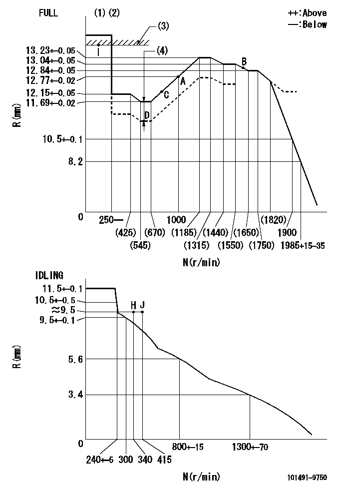
N:Pump speed
R:Rack position (mm)
(1)Torque cam stamping: T1
(2)Tolerance for racks not indicated: R1, speed N1
(3)RACK LIMIT
(4)Boost compensator stroke: BCL
----------
T1=C60 R1=+-0.02mm N1=+-3r/min BCL=1.2+-0.1mm
----------
----------
T1=C60 R1=+-0.02mm N1=+-3r/min BCL=1.2+-0.1mm
----------
Speed control lever angle

F:Full speed
I:Idle
(1)Use the hole at R = aa
(2)Stopper bolt setting
----------
aa=36mm
----------
a=20deg+-5deg b=43deg+-3deg
----------
aa=36mm
----------
a=20deg+-5deg b=43deg+-3deg
Stop lever angle
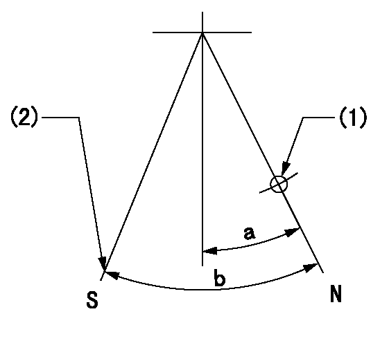
N:Pump normal
S:Stop the pump.
(1)Use the hole at R = aa
(2)Set the stop adjuster screw
----------
aa=39mm
----------
a=14deg+-5deg b=(29deg)+-5deg
----------
aa=39mm
----------
a=14deg+-5deg b=(29deg)+-5deg
0000001501 GOV RACK POSITION CONFIRM
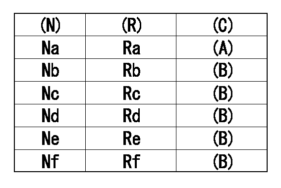
Confirm the governor adjustment rack position.
(N): Speed of the pump
(R) Rack position (mm)
Standard point A
(B) Confirmation
Remarks C
----------
----------
Na=1000r/min Nb=625r/min Nc=1700r/min Nd=1500r/min Ne=1250r/min Nf=400r/min Ra=12.77+-0.02mm Rb=11.69+-0.02mm Rc=12.84+-0.05mm Rd=13.04+-0.05mm Re=13.23+-0.05mm Rf=12.15+-0.05mm
----------
----------
Na=1000r/min Nb=625r/min Nc=1700r/min Nd=1500r/min Ne=1250r/min Nf=400r/min Ra=12.77+-0.02mm Rb=11.69+-0.02mm Rc=12.84+-0.05mm Rd=13.04+-0.05mm Re=13.23+-0.05mm Rf=12.15+-0.05mm
0000001601 LEVER
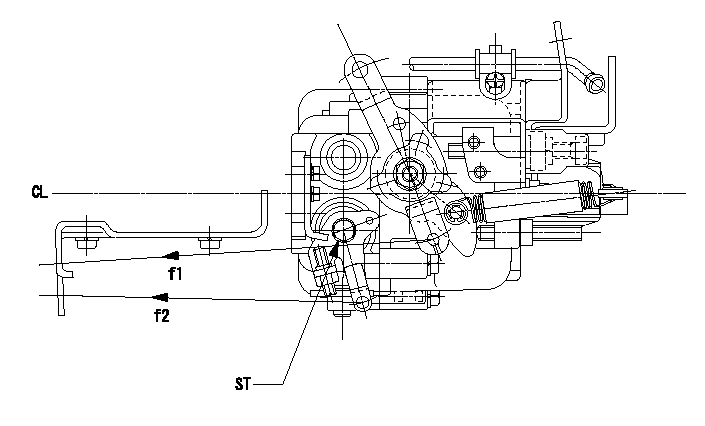
CL:Center line of camshaft
ST:Stop adjuster screw
f1:Direction for pulling the speed lever
f2:Direction for pulling the stop lever
1. Stop lever adjustment outline
(1)After completing all adjustments, confirm that the lever angle is within the specifications in the normal position.
(2)Set the speed lever in the full speed position.
(3)At pump speed Na, position the rack at non-injection position Ra.
(4)Set the stop adjusting screw to fix the speed lever in the idling position.
(5)Confirm that there is no injection at pump speed Nb.
----------
Na=1825r/min Nb=340r/min Ra=5.1+-0.3mm
----------
----------
Na=1825r/min Nb=340r/min Ra=5.1+-0.3mm
----------
Timing setting

(1)Pump vertical direction
(2)Position of gear mark 'CC' at No 1 cylinder's beginning of injection
(3)B.T.D.C.: aa
(4)-
----------
aa=11deg
----------
a=(130deg)
----------
aa=11deg
----------
a=(130deg)
Information:
Industrial Rating Definitions
The application examples are listed for reference only. Refer to the specific application information and guidelines within the Technical Marketing Information for exact rating determination.A Rating (Continuous)
* For heavy-duty service when engine is operated at rated load and speed up to 100 percent of the time without interruption or load cycling.* Time at full load up to 100 percent of the duty cycle.* Typical examples are: pipeline pumping, ventilation, and customer specifications.B Rating
* For servicing where power and/or speed are cyclic.* Time at full load not to exceed 80 percent of the duty cycle.* Typical examples are: irrigation where normal pump demand is 85 percent of the duty cycle, oil field mechanical pumping and drilling, and stationary/plant air compressors.C Rating (Intermittent)
* For service where power and/or speed are cyclic* The horsepower and speed capability of the engine can be used for one uninterrupted hour, followed by one hour of operation at or below the A rating.* Time at full load not to exceed 50 percent of the duty cycle.* Typical examples are: agricultural tractors, harvesters and combines, off-highway trucks, fire pump application power, blast hole drills, rock crushers and wood chippers with high torque rise, and oil field hoisting.D Rating
* For service when rated power is required for periodic overloads.* The maximum horsepower and speed capability of the engine can be used for a maximum of 30 uninterrupted minutes, followed by one hour of followed by one hour of C rating operation.* Time at full load not to exceed 10 percent of the duty cycle.* Typical examples are: offshore cranes, runway snow blowers, water well drills, portable air compressors, and fire pump certification power.E Rating
* For service where rated power is required for a short time for initial starting or sudden overload. For emergency service where standard power is unavailable.* The maximum horsepower and speed capability of the engine can be utilized for a maximum of 15 uninterrupted minutes, followed by one hour at C rating operation, or for the duration of the emergency.* Time at full load is not to exceed 5 percent of the duty cycle.* Typical examples are: standby centrifugal water pumps, oil field well servicing, crash trucks, and gas turbine starters.Rating Conditions
Unless otherwise specified, all ratings are based on SAE J1349 standard ambient conditions:* 100 kPa (29.6 inches of Hg) of pressure* 30 percent relative humidity, and* a temperature of 26°C (77°F).Ratings also apply at AS1501, BS5514, DIN6271, and ISO3046/1 standard conditions.Power for diesel engines is based on:* API gravity of 35 at 15°C (60°F),* fuel LHV of 42.780 kJ/g (18390 Btu/lb) at 29°C (84°F), and* fuel density of 838.9 g/L (7.0001 lb/US gal)Ratings are gross output ratings- the total output capability of the engine-equipped with standard accessories. Standard accessories include pumps for lubrication oil, fuel, and jacket water, and magneto as required. The gross output, minus the power required to drive auxiliary components, equals the net power available for the external (flywheel) load. Typical auxiliary components include cooling fans, air compressors,