Information injection-pump assembly
ZEXEL
101491-9611
1014919611
NISSAN-DIESEL
1670054T64
1670054t64
Rating:
Service parts 101491-9611 INJECTION-PUMP ASSEMBLY:
1.
_
6.
COUPLING PLATE
7.
COUPLING PLATE
8.
_
9.
_
11.
Nozzle and Holder
16600-54T01
12.
Open Pre:MPa(Kqf/cm2)
18.1{185}
15.
NOZZLE SET
Cross reference number
ZEXEL
101491-9611
1014919611
NISSAN-DIESEL
1670054T64
1670054t64
Zexel num
Bosch num
Firm num
Name
101491-9611
1670054T64 NISSAN-DIESEL
INJECTION-PUMP ASSEMBLY
BD2 * K 14BC PE4A,5A, PE
BD2 * K 14BC PE4A,5A, PE
Calibration Data:
Adjustment conditions
Test oil
1404 Test oil ISO4113 or {SAEJ967d}
1404 Test oil ISO4113 or {SAEJ967d}
Test oil temperature
degC
40
40
45
Nozzle and nozzle holder
105780-8140
Bosch type code
EF8511/9A
Nozzle
105780-0000
Bosch type code
DN12SD12T
Nozzle holder
105780-2080
Bosch type code
EF8511/9
Opening pressure
MPa
17.2
Opening pressure
kgf/cm2
175
Injection pipe
Outer diameter - inner diameter - length (mm) mm 6-2-600
Outer diameter - inner diameter - length (mm) mm 6-2-600
Overflow valve opening pressure
kPa
157
123
191
Overflow valve opening pressure
kgf/cm2
1.6
1.25
1.95
Tester oil delivery pressure
kPa
157
157
157
Tester oil delivery pressure
kgf/cm2
1.6
1.6
1.6
Direction of rotation (viewed from drive side)
Right R
Right R
Injection timing adjustment
Direction of rotation (viewed from drive side)
Right R
Right R
Injection order
1-3-4-2
Pre-stroke
mm
3.2
3.15
3.25
Beginning of injection position
Drive side NO.1
Drive side NO.1
Difference between angles 1
Cal 1-3 deg. 90 89.5 90.5
Cal 1-3 deg. 90 89.5 90.5
Difference between angles 2
Cal 1-4 deg. 180 179.5 180.5
Cal 1-4 deg. 180 179.5 180.5
Difference between angles 3
Cyl.1-2 deg. 270 269.5 270.5
Cyl.1-2 deg. 270 269.5 270.5
Injection quantity adjustment
Adjusting point
-
Rack position
11.5
Pump speed
r/min
1000
1000
1000
Average injection quantity
mm3/st.
53.6
52
55.2
Max. variation between cylinders
%
0
-2.5
2.5
Basic
*
Fixing the rack
*
Standard for adjustment of the maximum variation between cylinders
*
Injection quantity adjustment_02
Adjusting point
H
Rack position
9.5+-0.5
Pump speed
r/min
350
350
350
Average injection quantity
mm3/st.
8
6.9
9.1
Max. variation between cylinders
%
0
-15
15
Fixing the rack
*
Standard for adjustment of the maximum variation between cylinders
*
Injection quantity adjustment_03
Adjusting point
A
Rack position
R1(11.5)
Pump speed
r/min
1000
1000
1000
Average injection quantity
mm3/st.
53.6
52.5
54.7
Basic
*
Fixing the lever
*
Injection quantity adjustment_04
Adjusting point
B
Rack position
R1-0.2
Pump speed
r/min
1900
1900
1900
Average injection quantity
mm3/st.
53.2
49.2
57.2
Fixing the lever
*
Injection quantity adjustment_05
Adjusting point
I
Rack position
-
Pump speed
r/min
100
100
100
Average injection quantity
mm3/st.
69
64
74
Fixing the lever
*
Rack limit
*
Timer adjustment
Pump speed
r/min
950--
Advance angle
deg.
0
0
0
Remarks
Start
Start
Timer adjustment_02
Pump speed
r/min
900
Advance angle
deg.
0.5
Timer adjustment_03
Pump speed
r/min
1900
Advance angle
deg.
5
4.5
5.5
Remarks
Finish
Finish
Test data Ex:
Governor adjustment
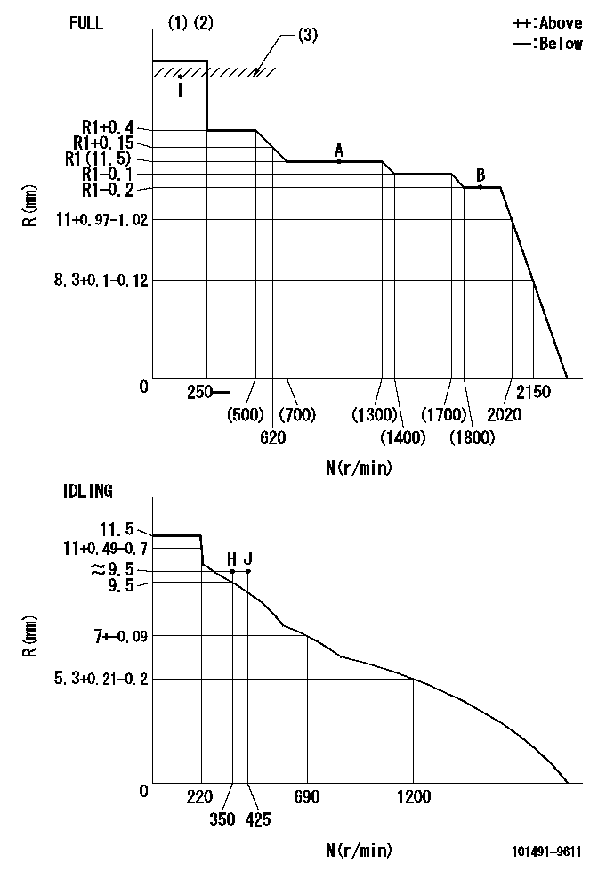
N:Pump speed
R:Rack position (mm)
(1)Torque cam stamping: T1
(2)Tolerance for racks not indicated: +-0.05mm.
(3)RACK LIMIT
----------
T1=D81
----------
----------
T1=D81
----------
Speed control lever angle
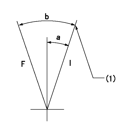
F:Full speed
I:Idle
(1)Stopper bolt setting
----------
----------
a=20deg+-5deg b=38deg+-3deg
----------
----------
a=20deg+-5deg b=38deg+-3deg
Stop lever angle
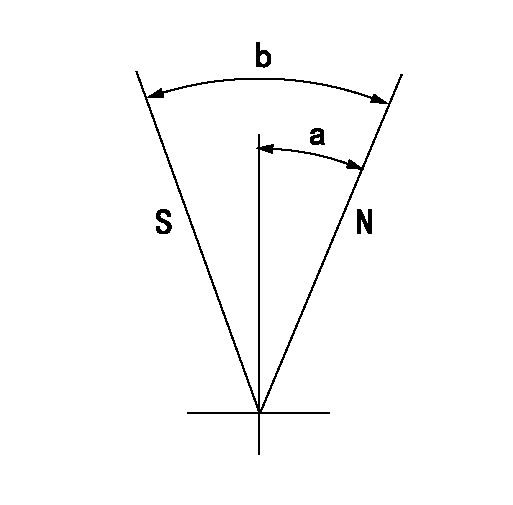
N:Pump normal
S:Stop the pump.
----------
----------
a=5deg+-5deg b=29deg+-5deg
----------
----------
a=5deg+-5deg b=29deg+-5deg
Timing setting

(1)Pump vertical direction
(2)Position of gear mark 'ZZ' at No 1 cylinder's beginning of injection
(3)B.T.D.C.: aa
(4)-
----------
aa=14deg
----------
a=(100deg)
----------
aa=14deg
----------
a=(100deg)
Information:
Refer to the topics in the Operation & Maintenance Manual, SEBU6150, SR4 Generators and Control Panels, and the Maintenance Schedules in this manual for page numbers and information to perform the maintenance specified in the following schedules.Weekly (Before Starting Engine)
Walk-Around Inspection - Inspect engine for leaks and loose connections Engine Crankcase - Check oil level Cooling System - Check coolant level Battery Charger - Check for proper operation Batteries - Clean/Check electrolyte level Air Starter System (if equipped) - Check lubricator oil level, air pressure and drain condensation Engine Air Cleaner - Check service indicator Block Heater - Check for proper operation, maintain 32°C (90°F) temperature Aftercooler - Inspect ATAAC Belts - Inspect/Replace Engine Protection Devices - Inspect system and gauges for proper operation Generator and Control Panel - Inspect componentsWeekly (With Engine Running)*
Walk-Around Inspection - Inspect engine for leaks and loose connections and generator louvers for proper operation Engine Crankcase - Check oil level Oil Pressure - Check gauge reading Generator - Check frequency (rpm) and generated voltageWeekly (After Stopping Engine)*
Walk-Around Inspection - Inspect engine and report malfunction and make necessary repairs Automatic Switches - Check for proper position to execute auto-start Battery Charger - Record charging amperage readingYearly (Before Starting Engine)*
Cooling System - Check coolant level, Test for concentration of supplemental coolant additive Crankcase Breather - Clean Valve Lash - Check/Adjust Governor - Inspect for leaks Governor Linkage - Check/Adjust and Lubricate Air Inlet Piping - Inspect Engine Air Cleaner - Check service indicator, Replace element if necessary Generator - Lubricate bearingYearly (With Engine Running)*
Engine Protection Devices - Inspect system and gauges for proper operation;/bs/, Record gauge readings Radiator (If Equipped) - Inspect for leaks and loose connections and louvers for proper operation Load Test - Operate the engine at a minimum of 30 percent of rated load for minimum of two hours Engine Mounts - InspectYearly (After Stopping Engine)*
Scheduled Oil Sampling (S O S) Analysis - Obtain Engine Oil and Filters - ReplaceEvery Three Years (Before Starting Engine)*
Turbocharger - Inspect/Check bearing end play and radial clearance Governor - Inspect for leaks Thermostat - Replace Coolant Hoses - Replace Cooling System - Clean/Flush coolant Batteries - ReplaceEvery Three Years (With Engine Running)*
Walk-Around Inspection - Inspect engine for leaks and loose connections Engine Protection Devices - Inspect system and gauges for proper operation, Record gauge readings Engine Crankcase - Check oil level Radiator (If Equipped) - Inspect for leaks and loose connections and louvers for proper operation Load Test - Operate at a minimum of 30 percent of rated load for minimum of two hours Exhaust System - Check for leaksEvery Three Years (After Stopping Engine)*
Walk-Around Inspection - Inspect engine and report malfunction and make necessary repairs Scheduled Oil Sampling (S O S) Analysis - Obtain Engine Oil and Filters - Replace Battery Charger - Record charging amp reading Automatic Switches - Check for proper position to execute auto-start Coolant Analysis - ObtainEvery Four Years
Drain/Replace Engine Coolant (Extended Life Coolant Only)*First Perform Previous Maintenance Items
Have questions with 101491-9611?
Group cross 101491-9611 ZEXEL
Mazda
Mazda
Nissan-Diesel
101491-9611
1670054T64
INJECTION-PUMP ASSEMBLY
BD2
BD2
