Information injection-pump assembly
ZEXEL
101491-9271
1014919271

Rating:
Cross reference number
ZEXEL
101491-9271
1014919271
Zexel num
Bosch num
Firm num
Name
Calibration Data:
Adjustment conditions
Test oil
1404 Test oil ISO4113 or {SAEJ967d}
1404 Test oil ISO4113 or {SAEJ967d}
Test oil temperature
degC
40
40
45
Nozzle and nozzle holder
105780-8140
Bosch type code
EF8511/9A
Nozzle
105780-0000
Bosch type code
DN12SD12T
Nozzle holder
105780-2080
Bosch type code
EF8511/9
Opening pressure
MPa
17.2
Opening pressure
kgf/cm2
175
Injection pipe
Outer diameter - inner diameter - length (mm) mm 6-2-600
Outer diameter - inner diameter - length (mm) mm 6-2-600
Overflow valve
131424-3420
Overflow valve opening pressure
kPa
255
221
289
Overflow valve opening pressure
kgf/cm2
2.6
2.25
2.95
Tester oil delivery pressure
kPa
157
157
157
Tester oil delivery pressure
kgf/cm2
1.6
1.6
1.6
Direction of rotation (viewed from drive side)
Right R
Right R
Injection timing adjustment
Direction of rotation (viewed from drive side)
Right R
Right R
Injection order
1-3-4-2
Pre-stroke
mm
3.2
3.15
3.25
Beginning of injection position
Drive side NO.1
Drive side NO.1
Difference between angles 1
Cal 1-3 deg. 90 89.5 90.5
Cal 1-3 deg. 90 89.5 90.5
Difference between angles 2
Cal 1-4 deg. 180 179.5 180.5
Cal 1-4 deg. 180 179.5 180.5
Difference between angles 3
Cyl.1-2 deg. 270 269.5 270.5
Cyl.1-2 deg. 270 269.5 270.5
Injection quantity adjustment
Adjusting point
-
Rack position
12.5
Pump speed
r/min
1000
1000
1000
Average injection quantity
mm3/st.
74
73.5
74.5
Max. variation between cylinders
%
0
-2.5
2.5
Basic
*
Fixing the rack
*
Standard for adjustment of the maximum variation between cylinders
*
Injection quantity adjustment_02
Adjusting point
H
Rack position
9.5+-0.5
Pump speed
r/min
300
300
300
Average injection quantity
mm3/st.
8
6
10
Max. variation between cylinders
%
0
-14
14
Fixing the rack
*
Standard for adjustment of the maximum variation between cylinders
*
Injection quantity adjustment_03
Adjusting point
A
Rack position
R1(12.5)
Pump speed
r/min
1000
1000
1000
Average injection quantity
mm3/st.
74
73.5
74.5
Basic
*
Fixing the lever
*
Boost pressure
kPa
20
20
Boost pressure
mmHg
150
150
Injection quantity adjustment_04
Adjusting point
B
Rack position
(R1+0.6)
Pump speed
r/min
1600
1600
1600
Average injection quantity
mm3/st.
87.6
83.6
91.6
Fixing the lever
*
Boost pressure
kPa
20
20
Boost pressure
mmHg
150
150
Injection quantity adjustment_05
Adjusting point
I
Rack position
-
Pump speed
r/min
100
100
100
Average injection quantity
mm3/st.
75
70
85
Fixing the lever
*
Rack limit
*
Boost compensator adjustment
Pump speed
r/min
1400
1400
1400
Rack position
R1-0.35
Boost pressure
kPa
2
2
4.7
Boost pressure
mmHg
15
15
35
Boost compensator adjustment_02
Pump speed
r/min
1400
1400
1400
Rack position
R1+0.85
Boost pressure
kPa
11.3
11.3
11.3
Boost pressure
mmHg
85
85
85
Timer adjustment
Pump speed
r/min
850+-25
Advance angle
deg.
1
0.7
1.3
Remarks
Start
Start
Timer adjustment_02
Pump speed
r/min
925
Advance angle
deg.
0.3
Timer adjustment_03
Pump speed
r/min
1400+-25
Advance angle
deg.
0
0
0
Timer adjustment_04
Pump speed
r/min
1700+-25
Advance angle
deg.
3.5
3.2
3.8
Remarks
Finish
Finish
Test data Ex:
Governor adjustment
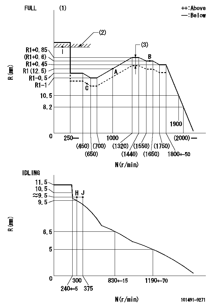
N:Pump speed
R:Rack position (mm)
(1)Torque cam stamping: T1
(2)RACK LIMIT
(3)Boost compensator stroke: BCL
----------
T1=B80 T1=1.2+-0.1mm
----------
----------
T1=B80 T1=1.2+-0.1mm
----------
Speed control lever angle

F:Full speed
I:Idle
(1)Stopper bolt set position 'H'
----------
----------
a=20deg+-5deg b=(38deg)+-3deg
----------
----------
a=20deg+-5deg b=(38deg)+-3deg
Stop lever angle
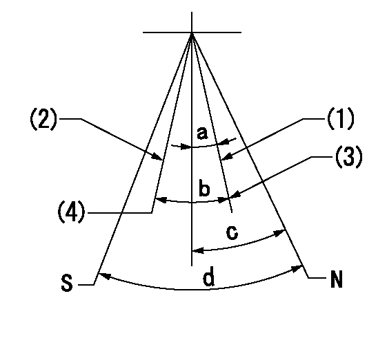
N:Pump normal
S:Stop the pump.
(1)Normal
(2)Stop
(3)Set the normal set bolt.
(4)Set the speed to aa using the idle lever and then confirm non-injection.
----------
aa=300r/min
----------
a=(15deg)+-5deg b=(13.5deg) c=23deg+-5deg d=40deg+-5deg
----------
aa=300r/min
----------
a=(15deg)+-5deg b=(13.5deg) c=23deg+-5deg d=40deg+-5deg
0000001501 LEVER
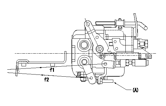
f1:Direction for pulling the speed lever
f2:Direction for pulling the stop lever
Stop lever's normal position setting method
1. (1) Push in the set bolt (A) until the rack starts to move.
(2)Return the bolt N1 turns from that position and set.
2. Rack with limiter
(1)Return the bolt N1 turns from the rack limit position and set.
----------
N1=1.5
----------
----------
N1=1.5
----------
Timing setting

(1)Pump vertical direction
(2)Position of gear mark 'CC' at No 1 cylinder's beginning of injection
(3)-
(4)-
----------
----------
a=(130deg)
----------
----------
a=(130deg)
Information:
Start By:a. remove radiator 1. Remove the four bolts and remove fan blade (1) and extension. 2. Loosen bolts (2) and remove fan belt (4). Loosen clamps (3) and disconnect the two hoses. Remove nut (5) from water pump fan pulley (6). 3. Install tooling (A) and remove fan pulley (6). 4. Remove four bolts (7) and remove the water pump and gasket. At the time of assembly, tighten nut (5) to the torque of 80 N m (60 lb.ft.) Install in the reverse order.Disassemble Water Pump
Start By:a. remove water pump 1. Remove key (1) from the shaft. 2. Remove pump housing (2) from the rear housing. 3. Remove snap ring (3) with tool (A). 4. Put the water pump housing in position on a press. Install tool (B) and remove the shaft assembly from the impeller and water pump housing. 5. Remove seals (4) from the water pump housing if they are damaged. 6. Put shaft assembly (5) in position in a press. Install tool (B) and remove bearings (6) and spacer (7) from the shaft.Assemble Water Pump
1. Put one of the shaft's bearings in position in a press. Make sure there is support for the inner race of the bearing. Push shaft (1) on to bearing (2). 2. Install spacer (4) on the shaft. Put second bearing (3) in position and push the shaft on to it. 3. Install seal (6) and flange (5) in the water pump housing. 4. Put 2S3230 Bearing Lubricant on the bearings. Put the water pump housing in position on a press and install shaft assembly (7) in the housing. 5. Install snap ring (8) over the bearings with tool (A). 6. Install the water seal in the housing with tooling (B). 7. Install seal (9) on the shaft assembly. 8. Install impeller (10) on the shaft with tooling (C) and a press. The clearance between the impeller blade and pump body must be 0.30 to 0.81 mm (.012 to .032 in). 9. Install a new gasket on water pump housing (12). Install housing (12) on the rear housing with nuts (11) that hold it. 10. Install key (13) in the shaft.End By:a. install water pump