Information injection-pump assembly
ZEXEL
101491-9232
1014919232
Rating:
Cross reference number
ZEXEL
101491-9232
1014919232
Zexel num
Bosch num
Firm num
Name
101491-9232
INJECTION-PUMP ASSEMBLY
Calibration Data:
Adjustment conditions
Test oil
1404 Test oil ISO4113 or {SAEJ967d}
1404 Test oil ISO4113 or {SAEJ967d}
Test oil temperature
degC
40
40
45
Nozzle and nozzle holder
105780-8140
Bosch type code
EF8511/9A
Nozzle
105780-0000
Bosch type code
DN12SD12T
Nozzle holder
105780-2080
Bosch type code
EF8511/9
Opening pressure
MPa
17.2
Opening pressure
kgf/cm2
175
Injection pipe
Outer diameter - inner diameter - length (mm) mm 6-2-600
Outer diameter - inner diameter - length (mm) mm 6-2-600
Overflow valve opening pressure
kPa
157
123
191
Overflow valve opening pressure
kgf/cm2
1.6
1.25
1.95
Tester oil delivery pressure
kPa
157
157
157
Tester oil delivery pressure
kgf/cm2
1.6
1.6
1.6
Direction of rotation (viewed from drive side)
Right R
Right R
Injection timing adjustment
Direction of rotation (viewed from drive side)
Right R
Right R
Injection order
1-3-4-2
Pre-stroke
mm
3.4
3.35
3.45
Beginning of injection position
Drive side NO.1
Drive side NO.1
Difference between angles 1
Cal 1-3 deg. 90 89.5 90.5
Cal 1-3 deg. 90 89.5 90.5
Difference between angles 2
Cal 1-4 deg. 180 179.5 180.5
Cal 1-4 deg. 180 179.5 180.5
Difference between angles 3
Cyl.1-2 deg. 270 269.5 270.5
Cyl.1-2 deg. 270 269.5 270.5
Injection quantity adjustment
Adjusting point
-
Rack position
11.28+-0
.02
Pump speed
r/min
1000
1000
1000
Average injection quantity
mm3/st.
57.7
57.2
58.2
Max. variation between cylinders
%
0
-2.5
2.5
Basic
*
Fixing the rack
*
Standard for adjustment of the maximum variation between cylinders
*
Injection quantity adjustment_02
Adjusting point
-
Rack position
9.6+-0.5
Pump speed
r/min
325
325
325
Average injection quantity
mm3/st.
9
7
11
Max. variation between cylinders
%
0
-14
14
Fixing the rack
*
Standard for adjustment of the maximum variation between cylinders
*
Remarks
Adjust only variation between cylinders; adjust governor according to governor specifications.
Adjust only variation between cylinders; adjust governor according to governor specifications.
Injection quantity adjustment_03
Adjusting point
A
Rack position
11.28+-0
.5
Pump speed
r/min
1000
1000
1000
Average injection quantity
mm3/st.
57.7
57.2
58.2
Basic
*
Fixing the lever
*
Injection quantity adjustment_04
Adjusting point
B
Rack position
11.55+-0
.5
Pump speed
r/min
1700
1700
1700
Average injection quantity
mm3/st.
70
68
72
Fixing the lever
*
Injection quantity adjustment_05
Adjusting point
C
Rack position
11.39+-0
.5
Pump speed
r/min
625
625
625
Average injection quantity
mm3/st.
42.9
40.9
44.9
Fixing the lever
*
Injection quantity adjustment_06
Adjusting point
I
Rack position
15++
Pump speed
r/min
100
100
100
Average injection quantity
mm3/st.
106
96
116
Fixing the lever
*
Injection quantity adjustment_07
Adjusting point
H
Rack position
9.3+-0.5
Pump speed
r/min
325
325
325
Average injection quantity
mm3/st.
7
6.5
7.5
Fixing the lever
*
Timer adjustment
Pump speed
r/min
1350+-25
Advance angle
deg.
0
0
0
Remarks
Start
Start
Timer adjustment_02
Pump speed
r/min
1700
Advance angle
deg.
3.5
3.2
3.8
Remarks
Finish
Finish
Test data Ex:
Governor adjustment
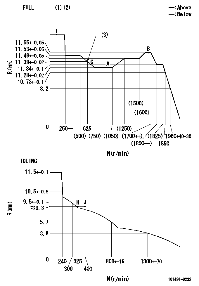
N:Pump speed
R:Rack position (mm)
(1)Torque cam stamping: T1
(2)Tolerance for racks not indicated: R1, speed N1
(3)Torque cam set point
----------
T1=C83 R1=+-0.02mm N1=+-3r/min
----------
----------
T1=C83 R1=+-0.02mm N1=+-3r/min
----------
Speed control lever angle

F:Full speed
I:Idle
(1)Stopper bolt set position 'H' (rack position = aa, speed = bb)
----------
aa=(9.3)mm bb=325r/min
----------
a=20deg+-5deg b=41deg+-3deg
----------
aa=(9.3)mm bb=325r/min
----------
a=20deg+-5deg b=41deg+-3deg
Stop lever angle
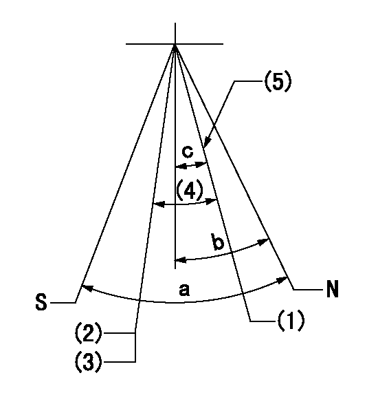
N:Pump normal
S:Stop the pump.
(1)Engine normal
(2)Engine stop
(3)Set the speed to aa using the idle lever and then confirm non-injection.
(4)(Actual measurement)
(5)Set the normal set bolt.
----------
aa=300r/min
----------
a=40deg+-5deg b=23deg+-5deg c=(17deg)+-5deg
----------
aa=300r/min
----------
a=40deg+-5deg b=23deg+-5deg c=(17deg)+-5deg
0000001501 GOV RACK POSITION CONFIRM
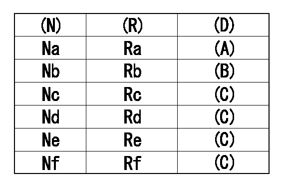
Confirm the governor adjustment rack position.
Standard point A
Set the torque cam B.
(C) Confirmation
(D) Remarks
(N): Speed of the pump
(R) Rack position (mm)
----------
----------
Na=1000r/min Nb=625r/min Nc=1800r/min Nd=1700r/min Ne=1400r/min Nf=450r/min Ra=11.28+-0.02mm Rb=11.39+-0.02mm Rc=11.34+-0.1mm Rd=11.55+-0.05mm Re=11.46+-0.05mm Rf=11.53+-0.05mm
----------
----------
Na=1000r/min Nb=625r/min Nc=1800r/min Nd=1700r/min Ne=1400r/min Nf=450r/min Ra=11.28+-0.02mm Rb=11.39+-0.02mm Rc=11.34+-0.1mm Rd=11.55+-0.05mm Re=11.46+-0.05mm Rf=11.53+-0.05mm
0000001601 LEVER
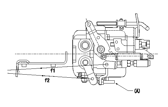
f1:Direction for pulling the speed lever
f2:Direction for pulling the stop lever
Stop lever's normal position setting method
1. (1) Push in the set bolt (A) until the rack starts to move.
(2)Return the bolt N1 turns from that position and set.
2. Rack with limiter
(1)Return the bolt N1 turns from the rack limit position and set.
----------
N1=1.5
----------
----------
N1=1.5
----------
Timing setting

(1)Pump vertical direction
(2)Position of gear mark 'CC' at No 1 cylinder's beginning of injection
(3)-
(4)-
----------
----------
a=(130deg)
----------
----------
a=(130deg)
Information:
Introduction
Tools are now available for the 6V4830 Fixture Group for removal and replacement of tappet springs on 3500 Unit Injectors.
Type 2 Fuel Injector. (1) Spring. (2) Rack Bar.
(3) 6V4830 Fixture Group. (4) 4C9279 Plate Assembly.Use fixture group (3) and plate assembly (4) along with the procedure in this instruction to remove and install tappet springs on injectors.Do not perform any procedure, outlined in this publication, or order any parts until you read and understand the information contained within.Removal and Installation of Fuel Injector Tappet Springs
Take care not to damage, drop, or jar the internal parts of the injector. Injector parts must be clean when reassembled. Place a light coating of clean diesel fuel, kerosene, or calibration fluid on the moving internal components during assembly.
* Clean the outside of the injector before disassembly. Install good O-ring seals on the injector and then install a 6V4172 Cleaning Sleeve. Wash the outside of the injector with solvents and a brush. Dry with pressure air.
Pressure air can cause personal injury. When using pressure air for cleaning, wear a protective face shield, protective clothing and protective shoes.The maximum air pressure must be below 205 kPa (30 psi) for cleaning purposes.
1. Remove existing plate and secure plate assembly (4) to fixture group (3).2. Remove O-ring seals from the injector prior to placing injector into fixture.3. Place injector into fixture with spring up as shown. Rack bar (2) on injector is to be extended out so that it is locked into position by two pins on plate assembly (4). 4. Using the handle of the fixture group, compress injector spring (tappet) (5) so that lock pin (6) can be pushed IN to release the tappet assembly from the injector body. 5. Remove tappet assembly from the injector body. Remove and discard old spring. Place the injector plunger on a soft clean cloth to avoid handling the plunger. Excessive handling will remove the fuel on the plunger and may result in corroding the plunger if it is left out for an extended period of time.6. Install new spring on injector body. 7. Locate the punched dot (.)(7) on the top end of the gear after it is pulled out of the body. Using a yellow magic marker, paint the whole length of the tooth that is 180° opposite the punched dot.
Injector Assembly (shown without spring).8. As the tappet/plunger assembly is inserted into the body, the yellow colored tooth on the gear should be visible in the center of the slot for the tappet lock pin.
Injector Assembly (shown without spring). 9. With the colored tooth visible in the slot of the injector body, a pin or long narrow screw driver is needed to position the gear to engage rack and pinion teeth after which the tappet assembly will drop into place.10. Using the 6V4830 Fixture Group, apply pressure on tappet (5) to compress the spring so the pin pops out and locks the tappet assembly in place.11. Remove the injector from the fixture. Push and pull the
Have questions with 101491-9232?
Group cross 101491-9232 ZEXEL
Nissan-Diesel
Mazda
Mazda
Mazda
101491-9232
INJECTION-PUMP ASSEMBLY