Information injection-pump assembly
ZEXEL
101491-9230
1014919230

Rating:
Cross reference number
ZEXEL
101491-9230
1014919230
Zexel num
Bosch num
Firm num
Name
101491-9230
MAZDA
INJECTION-PUMP ASSEMBLY
SL *
SL *
Calibration Data:
Adjustment conditions
Test oil
1404 Test oil ISO4113 or {SAEJ967d}
1404 Test oil ISO4113 or {SAEJ967d}
Test oil temperature
degC
40
40
45
Nozzle and nozzle holder
105780-8140
Bosch type code
EF8511/9A
Nozzle
105780-0000
Bosch type code
DN12SD12T
Nozzle holder
105780-2080
Bosch type code
EF8511/9
Opening pressure
MPa
17.2
Opening pressure
kgf/cm2
175
Injection pipe
Outer diameter - inner diameter - length (mm) mm 6-2-600
Outer diameter - inner diameter - length (mm) mm 6-2-600
Overflow valve opening pressure
kPa
157
123
191
Overflow valve opening pressure
kgf/cm2
1.6
1.25
1.95
Tester oil delivery pressure
kPa
157
157
157
Tester oil delivery pressure
kgf/cm2
1.6
1.6
1.6
Direction of rotation (viewed from drive side)
Right R
Right R
Injection timing adjustment
Direction of rotation (viewed from drive side)
Right R
Right R
Injection order
1-3-4-2
Pre-stroke
mm
3.4
3.35
3.45
Beginning of injection position
Drive side NO.1
Drive side NO.1
Difference between angles 1
Cal 1-3 deg. 90 89.5 90.5
Cal 1-3 deg. 90 89.5 90.5
Difference between angles 2
Cal 1-4 deg. 180 179.5 180.5
Cal 1-4 deg. 180 179.5 180.5
Difference between angles 3
Cyl.1-2 deg. 270 269.5 270.5
Cyl.1-2 deg. 270 269.5 270.5
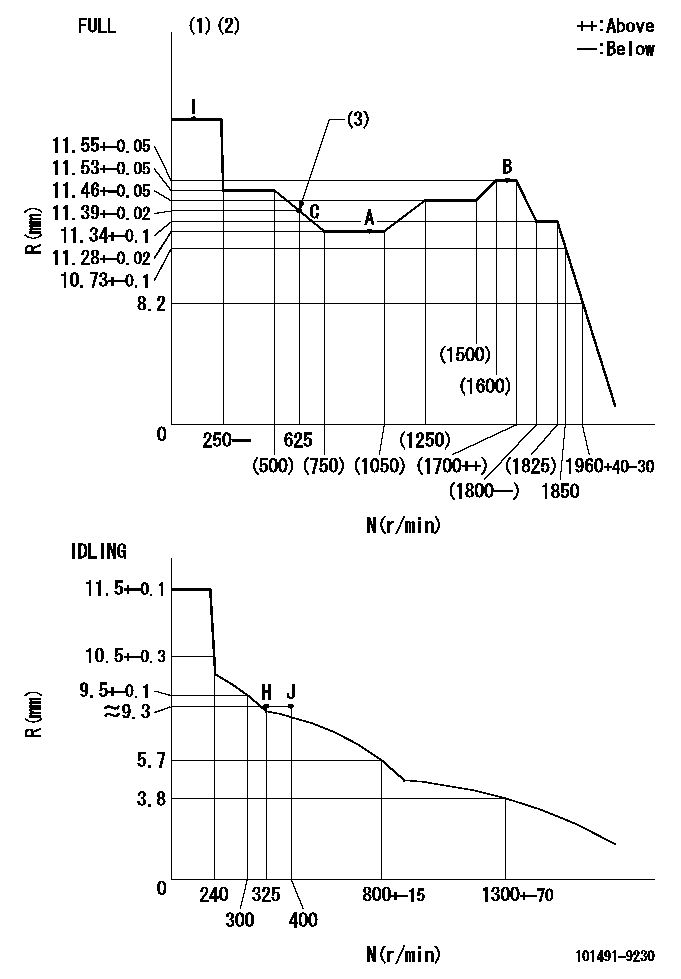
Injection quantity adjustment
Adjusting point
-
Rack position
11.28+-0
.02
Pump speed
r/min
1000
1000
1000
Average injection quantity
mm3/st.
57.7
57.2
58.2
Max. variation between cylinders
%
0
-2.5
2.5
Basic
*
Fixing the rack
*
Standard for adjustment of the maximum variation between cylinders
*
Injection quantity adjustment_02
Adjusting point
H
Rack position
9.3+-0.5
Pump speed
r/min
325
325
325
Average injection quantity
mm3/st.
9
7
11
Max. variation between cylinders
%
0
-14
14
Fixing the rack
*
Standard for adjustment of the maximum variation between cylinders
*
Injection quantity adjustment_03
Adjusting point
A
Rack position
11.28+-0
.5
Pump speed
r/min
1000
1000
1000
Average injection quantity
mm3/st.
57.7
57.2
58.2
Basic
*
Fixing the lever
*
Injection quantity adjustment_04
Adjusting point
B
Rack position
11.55+-0
.5
Pump speed
r/min
1700
1700
1700
Average injection quantity
mm3/st.
70
68
72
Fixing the lever
*
Injection quantity adjustment_05
Adjusting point
C
Rack position
11.39+-0
.5
Pump speed
r/min
625
625
625
Average injection quantity
mm3/st.
42.9
40.9
44.9
Fixing the lever
*
Injection quantity adjustment_06
Adjusting point
I
Rack position
15++
Pump speed
r/min
100
100
100
Average injection quantity
mm3/st.
106
96
116
Fixing the lever
*
Timer adjustment
Pump speed
r/min
1350+-25
Advance angle
deg.
0
0
0
Remarks
Start
Start
Timer adjustment_02
Pump speed
r/min
1700
Advance angle
deg.
3.5
3.2
3.8
Remarks
Finish
Finish
Test data Ex:
Governor adjustment
N:Pump speed
R:Rack position (mm)
(1)Torque cam stamping: T1
(2)Tolerance for racks not indicated: R1, speed N1
(3)Torque cam set point
----------
T1=A19 R1=+-0.02mm N1=+-3r/min
----------
----------
T1=A19 R1=+-0.02mm N1=+-3r/min
----------
Speed control lever angle

F:Full speed
I:Idle
(1)Stopper bolt set position 'H'
----------
----------
a=20deg+-5deg b=41deg+-3deg
----------
----------
a=20deg+-5deg b=41deg+-3deg
Stop lever angle
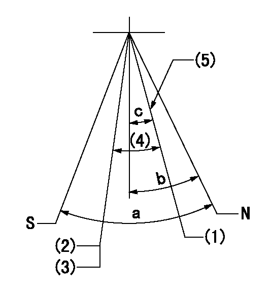
N:Pump normal
S:Stop the pump.
(1)Engine normal
(2)Engine stop
(3)Set the speed to aa using the idle lever and then confirm non-injection.
(4)(Actual measurement)
(5)Set the normal set bolt.
----------
aa=300r/min
----------
a=40deg+-5deg b=23deg+-5deg c=(17deg)+-5deg
----------
aa=300r/min
----------
a=40deg+-5deg b=23deg+-5deg c=(17deg)+-5deg
0000001501 GOV RACK POSITION CONFIRM
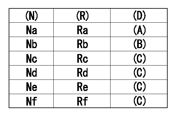
Confirm the governor adjustment rack position.
Standard point A
Set the torque cam B.
(C) Confirmation
(D) Remarks
(N): Speed of the pump
(R) Rack position (mm)
----------
----------
Na=1000r/min Nb=625r/min Nc=1800r/min Nd=1700r/min Ne=1400r/min Nf=450r/min Ra=11.28+-0.02mm Rb=11.39+-0.02mm Rc=11.34+-0.1mm Rd=11.55+-0.05mm Re=11.46+-0.05mm Rf=11.53+-0.05mm
----------
----------
Na=1000r/min Nb=625r/min Nc=1800r/min Nd=1700r/min Ne=1400r/min Nf=450r/min Ra=11.28+-0.02mm Rb=11.39+-0.02mm Rc=11.34+-0.1mm Rd=11.55+-0.05mm Re=11.46+-0.05mm Rf=11.53+-0.05mm
0000001601 LEVER
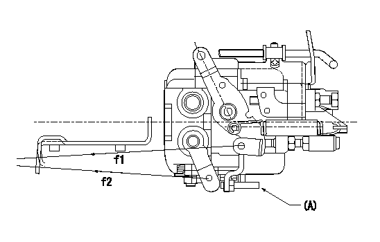
f1:Direction for pulling the speed lever
f2:Direction for pulling the stop lever
Stop lever's normal position setting method
1. (1) Push in the set bolt (A) until the rack starts to move.
(2)Return the bolt N1 turns from that position and set.
2. Rack with limiter
(1)Return the bolt N1 turns from the rack limit position and set.
----------
N1=1.5
----------
----------
N1=1.5
----------
Timing setting

(1)Pump vertical direction
(2)Position of gear mark 'CC' at No 1 cylinder's beginning of injection
(3)-
(4)-
----------
----------
a=(130deg)
----------
----------
a=(130deg)
Information:
Installation of Nozzles, Ether Supply Tubes and Connectors
1. If the machine does not already have an ether aid starting system, remove the plug from each turbocharger outlet adapter (2) and (3). Install a 3B6768 Bushing with a 7X1078 Nozzle Assembly (1) where each plug was removed. 2. When installing each nozzle assembly (1), the indicator mark at location (A) must be at the top as shown. Tighten the nozzle to a torque of 2.8 N m (25 lb in).3. Install 6Y1575 Tube Assembly (4) in the front nozzle and 6Y1576 Tube Assembly (6) in the rear nozzle as shown. Connect tube assemblies (4) and (6) to 8C9006 Tee (5). 4. Put 6Y1770 Tube Assembly (7) in position along the cylinder block and connect it to 8C9006 Tee (5) as shown. Install a 5P6312 Union (8) at the loose end as shown.5. Locate and attach 6V2686 Clips at locations (B) and (C), to secure tube (7) in position.6. Tighten the bolts that secure the clips at locations (B) and (C). 7. Put 5P0580 Tube (9) in position for connection to 5P6312 Union (8) that was JUST installed at the end of tube assembly (7). Position the tube assembly alongside chassis wiring harness (10) and up to the shuttle valve in cover assembly (11).Cut the 5P0580 Tube to length. Put a 5P6313 Nut and a 5P6314 Sleeve on the end of the piece of tube. Connect the end of the tube to union (8) and tighten the nut.
Be careful and DO NOT overtighten the nut. Overtightening the nut could crush the tube.
8. Use 3S2093 Straps (12) to fasten tube (9) to chassis wiring harness (10) [there are actually twelve straps between union (8) and the fender, and three straps inside of cover assembly (11)]. 9. Connect the end of tube (9) to elbow (13) in the outlet port of the shuttle valve. 10. If all welding procedures have been completed proceed as follows: * Apply the 9X4542 Ether Aid Identification Film (English) on the ECU. (If an Ether Aid Identification Film is needed for a language other than English, refer to the chart that follows for the part number to order to obtain a film with a specific language.) * Use four 5M3062 Bolts with 8T4896 Washers to fasten 9X5303 ECU (14) to the mounting bars inside cover assembly (11).* Connect the terminal on the loose end of fabricated wire assembly (15) (previously installed when mounting bars were installed inside the cover assembly) to one of the ECU mounting bolts as shown.* Connect the 30 pin connector of chassis wiring harness (10) to ECU (14).11. Use the dimensions shown to install 9X6191 Film (16).12. Put a 5P1075 Washer over the end of the 7S2043 Knob Assembly. Put the end of the knob assembly through the door of cover assembly (11). Install the 9S8230 Plate Assembly over the shaft of the knob assembly, then insert the 4H1641 Pin in the hole in the shaft.Installation of Ether Cylinders
1. Turn the disconnect switch
Have questions with 101491-9230?
Group cross 101491-9230 ZEXEL
Nissan-Diesel
Mazda
Mazda
Mazda
101491-9230
INJECTION-PUMP ASSEMBLY
SL
SL