Information injection-pump assembly
ZEXEL
101491-9220
1014919220

Rating:
Cross reference number
ZEXEL
101491-9220
1014919220
Zexel num
Bosch num
Firm num
Name
Calibration Data:
Adjustment conditions
Test oil
1404 Test oil ISO4113 or {SAEJ967d}
1404 Test oil ISO4113 or {SAEJ967d}
Test oil temperature
degC
40
40
45
Nozzle and nozzle holder
105780-8140
Bosch type code
EF8511/9A
Nozzle
105780-0000
Bosch type code
DN12SD12T
Nozzle holder
105780-2080
Bosch type code
EF8511/9
Opening pressure
MPa
17.2
Opening pressure
kgf/cm2
175
Injection pipe
Outer diameter - inner diameter - length (mm) mm 6-2-600
Outer diameter - inner diameter - length (mm) mm 6-2-600
Overflow valve opening pressure
kPa
157
123
191
Overflow valve opening pressure
kgf/cm2
1.6
1.25
1.95
Tester oil delivery pressure
kPa
157
157
157
Tester oil delivery pressure
kgf/cm2
1.6
1.6
1.6
Direction of rotation (viewed from drive side)
Right R
Right R
Injection timing adjustment
Direction of rotation (viewed from drive side)
Right R
Right R
Injection order
1-3-4-2
Pre-stroke
mm
3.4
3.35
3.45
Beginning of injection position
Drive side NO.1
Drive side NO.1
Difference between angles 1
Cal 1-3 deg. 90 89.5 90.5
Cal 1-3 deg. 90 89.5 90.5
Difference between angles 2
Cal 1-4 deg. 180 179.5 180.5
Cal 1-4 deg. 180 179.5 180.5
Difference between angles 3
Cyl.1-2 deg. 270 269.5 270.5
Cyl.1-2 deg. 270 269.5 270.5
Injection quantity adjustment
Adjusting point
-
Rack position
11.28+-0
.02
Pump speed
r/min
1000
1000
1000
Average injection quantity
mm3/st.
57.7
57.2
58.2
Max. variation between cylinders
%
0
-2.5
2.5
Basic
*
Fixing the rack
*
Standard for adjustment of the maximum variation between cylinders
*
Injection quantity adjustment_02
Adjusting point
H
Rack position
9.3+-0.5
Pump speed
r/min
325
325
325
Average injection quantity
mm3/st.
9
7
11
Max. variation between cylinders
%
0
-14
14
Fixing the rack
*
Standard for adjustment of the maximum variation between cylinders
*
Injection quantity adjustment_03
Adjusting point
A
Rack position
11.28+-0
.5
Pump speed
r/min
1000
1000
1000
Average injection quantity
mm3/st.
57.7
57.2
58.2
Basic
*
Fixing the lever
*
Injection quantity adjustment_04
Adjusting point
B
Rack position
11.55+-0
.5
Pump speed
r/min
1700
1700
1700
Average injection quantity
mm3/st.
70
68
72
Fixing the lever
*
Injection quantity adjustment_05
Adjusting point
C
Rack position
11.39+-0
.5
Pump speed
r/min
625
625
625
Average injection quantity
mm3/st.
42.9
40.9
44.9
Fixing the lever
*
Injection quantity adjustment_06
Adjusting point
I
Rack position
16.3+-0.
5
Pump speed
r/min
100
100
100
Average injection quantity
mm3/st.
91
81
96
Fixing the lever
*
Rack limit
*
Timer adjustment
Pump speed
r/min
1350+-25
Advance angle
deg.
0
0
0
Remarks
Start
Start
Timer adjustment_02
Pump speed
r/min
1700
Advance angle
deg.
3.5
3.2
3.8
Remarks
Finish
Finish
Test data Ex:
Governor adjustment
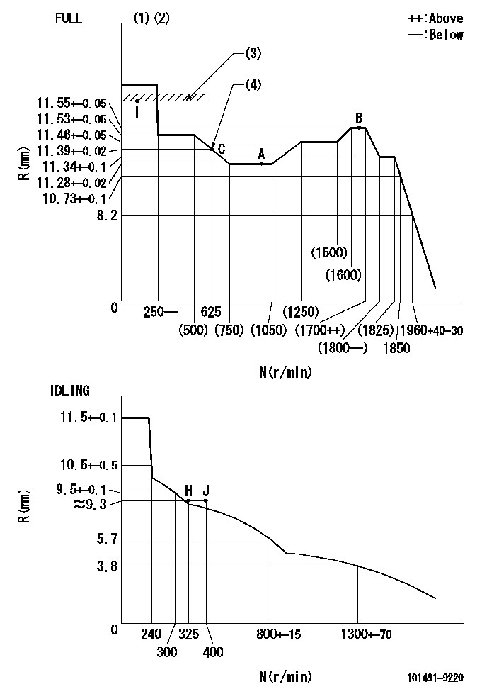
N:Pump speed
R:Rack position (mm)
(1)Torque cam stamping: T1
(2)Tolerance for racks not indicated: R1, speed N1
(3)RACK LIMIT
(4)Torque cam set point
----------
T1=A19 R1=+-0.02mm N1=+-3r/min
----------
----------
T1=A19 R1=+-0.02mm N1=+-3r/min
----------
Speed control lever angle

F:Full speed
I:Idle
(1)Stopper bolt set position 'H'
----------
----------
a=20deg+-5deg b=41deg+-3deg
----------
----------
a=20deg+-5deg b=41deg+-3deg
Stop lever angle
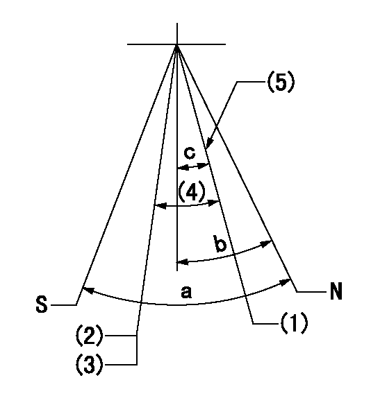
N:Pump normal
S:Stop the pump.
(1)Engine normal
(2)Engine stop
(3)Set the speed to aa using the idle lever and then confirm non-injection.
(4)(Actual measurement)
(5)Set the normal set bolt.
----------
aa=300r/min
----------
a=40deg+-5deg b=23deg+-5eg c=(15deg)+-5deg
----------
aa=300r/min
----------
a=40deg+-5deg b=23deg+-5eg c=(15deg)+-5deg
0000001501 GOV RACK POSITION CONFIRM
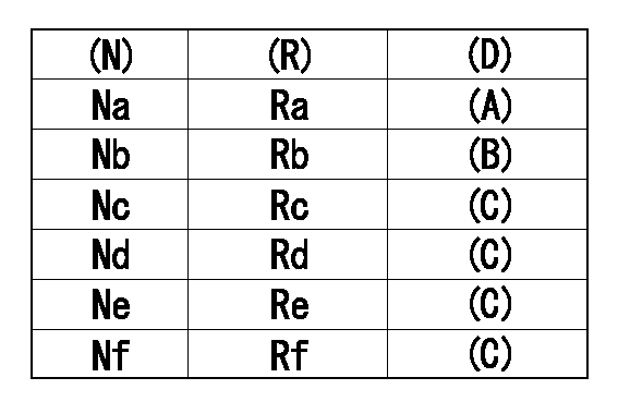
Confirm the governor adjustment rack position.
Standard point A
Set the torque cam B.
(C) Confirmation
(D) Remarks
(N): Speed of the pump
(R) Rack position (mm)
----------
----------
Na=1000r/min Nb=625r/min Nc=1800r/min Nd=1700r/min Ne=1400r/min Nf=450r/min Ra=11.28+-0.02mm Rb=11.39+-0.02mm Rc=11.34+-0.1mm Rd=11.55+-0.05mm Re=11.46+-0.05mm Rf=11.53+-0.05mm
----------
----------
Na=1000r/min Nb=625r/min Nc=1800r/min Nd=1700r/min Ne=1400r/min Nf=450r/min Ra=11.28+-0.02mm Rb=11.39+-0.02mm Rc=11.34+-0.1mm Rd=11.55+-0.05mm Re=11.46+-0.05mm Rf=11.53+-0.05mm
0000001601 LEVER
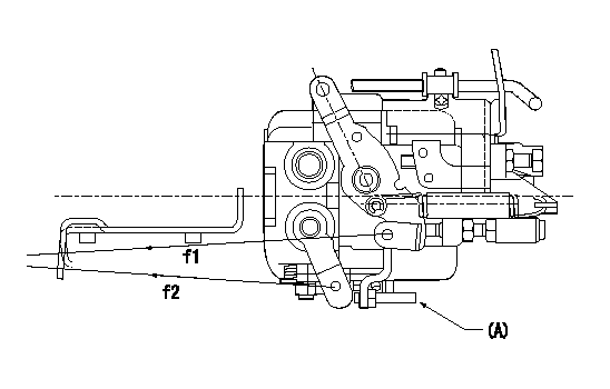
f1:Direction for pulling the speed lever
f2:Direction for pulling the stop lever
Stop lever's normal position setting method
1. (1) Push in the set bolt (A) until the rack starts to move.
(2)Return the bolt N1 turns from that position and set.
2. Rack with limiter
(1)Return the bolt N1 turns from the rack limit position and set.
----------
N1=1.5
----------
----------
N1=1.5
----------
Timing setting

(1)Pump vertical direction
(2)Position of gear mark 'CC' at No 1 cylinder's beginning of injection
(3)-
(4)-
----------
----------
a=(130deg)
----------
----------
a=(130deg)
Information:
ACTION REQUIRED
Before completing this Rework Procedure, please review the safety actions in the Operation and Maintenance Manual for your machine.
Choose one of the following actions:
Before Failure: If electronic unit fuel injectors have not failed, reflash the engine ECM with the new software. The new software offers enhanced protection to the fuel system if the fuel/water separator is not drained of water when the "Water Separator Full Indicator" is displayed.
After Failure: If electronic unit fuel injectors have failed, replace the injectors and reflash the engine ECM with the new software.
For detailed instructions on removing and installing the injectors, refer to UENR0633, Disassembly and Assembly, "Electronic Unit Injector - Remove" and "Electronic Unit Injector - Install".
SERVICE CLAIM ALLOWANCES
Product smu/age whichever comes first Caterpillar Dealer Suggested Customer Suggested
Parts % Labor Hrs% Parts % Labor Hrs% Parts % Labor Hrs%
*******Group 1*******
0-3000 hrs,
0-36 mo 100.0% 100.0% 0.0% 0.0% 0.0% 0.0%
This is a 1.0-hour job for Group 1
1 hour to update the software. An additional 3 hours is allowed to replace the injectors, after failure.
Product smu/age whichever comes first Caterpillar Dealer Suggested Customer Suggested
Parts % Labor Hrs% Parts % Labor Hrs% Parts % Labor Hrs%
*******Group 2*******
0-3000 hrs,
0-36 mo 100.0% 100.0% 0.0% 0.0% 0.0% 0.0%
This is a 1.0-hour job for Group 2
1 hour to update the software. An additional 3 hours is allowed to replace the injectors, after failure.
PARTS DISPOSITION
Handle the parts in accordance with your Warranty Bulletin on warranty parts handling.