Information injection-pump assembly
BOSCH
9 400 619 547
9400619547
ZEXEL
101491-9065
1014919065

Rating:
Service parts 101491-9065 INJECTION-PUMP ASSEMBLY:
1.
_
4.
SUPPLY PUMP
6.
COUPLING PLATE
7.
COUPLING PLATE
8.
_
9.
_
11.
Nozzle and Holder
SL0113640A
12.
Open Pre:MPa(Kqf/cm2)
16.7{170}
15.
NOZZLE SET
Cross reference number
BOSCH
9 400 619 547
9400619547
ZEXEL
101491-9065
1014919065
Zexel num
Bosch num
Firm num
Name
Calibration Data:
Adjustment conditions
Test oil
1404 Test oil ISO4113 or {SAEJ967d}
1404 Test oil ISO4113 or {SAEJ967d}
Test oil temperature
degC
40
40
45
Nozzle and nozzle holder
105780-8140
Bosch type code
EF8511/9A
Nozzle
105780-0000
Bosch type code
DN12SD12T
Nozzle holder
105780-2080
Bosch type code
EF8511/9
Opening pressure
MPa
17.2
Opening pressure
kgf/cm2
175
Injection pipe
Outer diameter - inner diameter - length (mm) mm 6-2-600
Outer diameter - inner diameter - length (mm) mm 6-2-600
Overflow valve opening pressure
kPa
157
123
191
Overflow valve opening pressure
kgf/cm2
1.6
1.25
1.95
Tester oil delivery pressure
kPa
157
157
157
Tester oil delivery pressure
kgf/cm2
1.6
1.6
1.6
Direction of rotation (viewed from drive side)
Right R
Right R
Injection timing adjustment
Direction of rotation (viewed from drive side)
Right R
Right R
Injection order
1-3-4-2
Pre-stroke
mm
3.4
3.35
3.45
Beginning of injection position
Drive side NO.1
Drive side NO.1
Difference between angles 1
Cal 1-3 deg. 90 89.5 90.5
Cal 1-3 deg. 90 89.5 90.5
Difference between angles 2
Cal 1-4 deg. 180 179.5 180.5
Cal 1-4 deg. 180 179.5 180.5
Difference between angles 3
Cyl.1-2 deg. 270 269.5 270.5
Cyl.1-2 deg. 270 269.5 270.5
Injection quantity adjustment
Adjusting point
-
Rack position
11.21+-0
.02
Pump speed
r/min
1000
1000
1000
Average injection quantity
mm3/st.
56.8
56.3
57.3
Max. variation between cylinders
%
0
-2.5
2.5
Basic
*
Fixing the rack
*
Standard for adjustment of the maximum variation between cylinders
*
Injection quantity adjustment_02
Adjusting point
H'
Rack position
9.6+-0.5
Pump speed
r/min
325
325
325
Average injection quantity
mm3/st.
9
7
11
Max. variation between cylinders
%
0
-14
14
Fixing the rack
*
Standard for adjustment of the maximum variation between cylinders
*
Injection quantity adjustment_03
Adjusting point
A
Rack position
11.21+-0
.5
Pump speed
r/min
1000
1000
1000
Average injection quantity
mm3/st.
56.8
56.3
57.3
Basic
*
Fixing the lever
*
Injection quantity adjustment_04
Adjusting point
B
Rack position
11.48+-0
.5
Pump speed
r/min
1700
1700
1700
Average injection quantity
mm3/st.
68.9
66.9
70.9
Fixing the lever
*
Injection quantity adjustment_05
Adjusting point
C
Rack position
11.32+-0
.5
Pump speed
r/min
625
625
625
Average injection quantity
mm3/st.
42
40
44
Fixing the lever
*
Injection quantity adjustment_06
Adjusting point
I
Rack position
16.3+-0.
5
Pump speed
r/min
100
100
100
Average injection quantity
mm3/st.
91
81
96
Fixing the lever
*
Rack limit
*
Injection quantity adjustment_07
Adjusting point
H
Rack position
9.3+-0.5
Pump speed
r/min
325
325
325
Average injection quantity
mm3/st.
7
6.5
7.5
Fixing the lever
*
Timer adjustment
Pump speed
r/min
1350+-25
Advance angle
deg.
0
0
0
Remarks
Start
Start
Timer adjustment_02
Pump speed
r/min
1700
Advance angle
deg.
3.5
3.2
3.8
Remarks
Finish
Finish
Test data Ex:
Governor adjustment
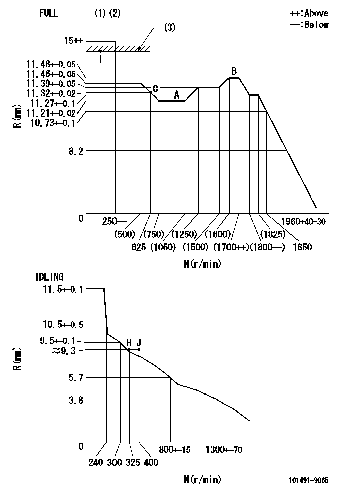
N:Pump speed
R:Rack position (mm)
(1)Torque cam stamping: T1
(2)Tolerance for racks not indicated: R1, speed N1
(3)RACK LIMIT
----------
T1=C83 R1=+-0.02mm N1=+-3r/min
----------
----------
T1=C83 R1=+-0.02mm N1=+-3r/min
----------
Speed control lever angle
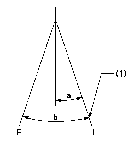
F:Full speed
I:Idle
(1)Set the stopper bolt (rack position = aa, speed = bb).
----------
aa=(9.3)mm bb=325r/min
----------
a=20deg+-5deg b=41deg+-3deg
----------
aa=(9.3)mm bb=325r/min
----------
a=20deg+-5deg b=41deg+-3deg
Stop lever angle
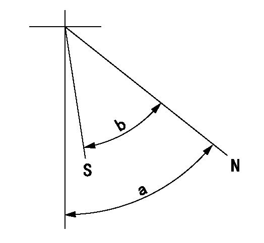
N:Pump normal
S:Stop the pump.
----------
----------
a=40deg+-5deg b=40deg+-5deg
----------
----------
a=40deg+-5deg b=40deg+-5deg
0000001501 GOV RACK POSITION CONFIRM
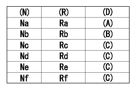
Confirm the governor adjustment rack position.
Standard point A
Set the torque cam B.
(C) Confirmation
(D) Remarks
(N): Speed of the pump
(R) Rack position (mm)
----------
----------
Na=1000r/min Nb=625r/min Nc=1800r/min Nd=1700r/min Ne=1400r/min Nf=450r/min Ra=11.21+-0.02mm Rb=11.32+-0.02mm Rc=11.27+-0.1mm Rd=11.48+-0.05mm Re=11.39+-0.05mm Rf=11.46+-0.05mm
----------
----------
Na=1000r/min Nb=625r/min Nc=1800r/min Nd=1700r/min Ne=1400r/min Nf=450r/min Ra=11.21+-0.02mm Rb=11.32+-0.02mm Rc=11.27+-0.1mm Rd=11.48+-0.05mm Re=11.39+-0.05mm Rf=11.46+-0.05mm
0000001601 ACS
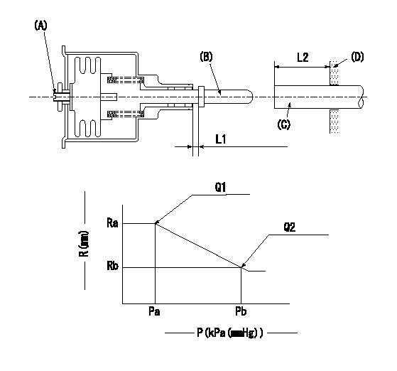
(A) Set screw
(B) Push rod 1
(C) Push rod 2
(D) Cover
1. Aneroid compensator unit adjustment
(1)Select the push rod 2 to obtain L2.
(2)Screw in (A) to obtain L1.
2. Adjustment when mounting the governor.
(1)Set the speed of the pump to N1 r/min and fix the control lever at the full set position.
(2)Screw in the aneroid compensator to obtain the performance shown in the graph above.
(3)As there is hysterisis, measure when the absolute pressure drops.
(4)Hysterisis must not exceed rack position = h1.
----------
N1=1000r/min L1=(1.5) mm L2=11+-0.5mm h1=-
----------
Ra=(11.21)mm Rb=(10.8)mm Pa=88.6+-2.7kPa(665+-20mmHg) Pb=79.4+-0.7kPa(596+-5mmHg) Q1=56.8+-0.5cm3/1000st Q2=48.8+-1cm3/1000st
----------
N1=1000r/min L1=(1.5) mm L2=11+-0.5mm h1=-
----------
Ra=(11.21)mm Rb=(10.8)mm Pa=88.6+-2.7kPa(665+-20mmHg) Pb=79.4+-0.7kPa(596+-5mmHg) Q1=56.8+-0.5cm3/1000st Q2=48.8+-1cm3/1000st
Timing setting
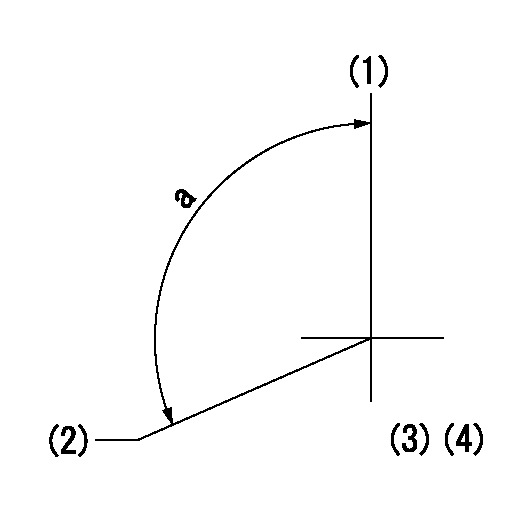
(1)Pump vertical direction
(2)Position of gear mark 'CC' at No 1 cylinder's beginning of injection
(3)B.T.D.C.: aa
(4)-
----------
aa=12.5deg
----------
a=(130deg)
----------
aa=12.5deg
----------
a=(130deg)
Information:
Problem
Certain 776B Tractors and 777B trucks may experience problems during cold starts. An Automatic Ether Injection System (AEIS) can be installed to improve starting and combustion during cold startups and increase the service life of the engine.
Affected Product
Model & Identification Number
776B (6JC1-83)
777B (4YC1-1383)
Parts Needed
2 - 3B6768 Bushing2 - 4N4274 Washer8 - 8C5607 Mount1 - 8C9006 Tee1 - 8C9812 Switch1 - 4D7794 Clip3 - 6D1641 Clip1 - 9D5659 Boss1 - 3E4930 Plate1 - 8E1415 Valve Assembly4 - 5G6966 Spacer4 - 9G3695 Plug5 - 9G9150 Clip1 - 9G9152 Clip3 - 9G9154 Clip1 - 9G9813 Alarm Group1 - 3J1907 Seal1 - 3J5390 Plug3 - 4K6177 Clip2 - 6K8180 Grommet1 - 4L6454 Bolt13 - 5M3062 Bolt8 - 9M8406 Clip3 - 7N0140 Tube Assembly2 - 7N9737 Housing2 - 7N9738 Housing1 - 8N1523 Lockwasher2 - 5P0598 Clamp2 - 5P2948 Connector1 - 5P4325 Clip4 - 5p6313 Nut4 - 5P6314 Sleeve1 - 5P6315 Elbow20 - 3S2093 Strap1 - 3T3046 Clip Assembly2 - 3T3048 Clip Assembly2 - 3T3133 Switch1 - 6T4361 Sensor8 - 8T4224 Washer14 - 8T4896 Washer8 - 8T9043 Bolt4 - 6V2686 Clip2 - 6V5066 Seal1 - 6V6809 Seal4 - 2W9499 Bolt1 - 8W8171 Tube1 - 8W8172 Tube1 - 8W8174 Tube2 - 7X0459 Screw1 - 7X0790 Tag2 - 7X1062 Cylinder Assembly2 - 7X1063 Orifice2 - 7X1078 Nozzle Assembly1 - 8X0912 Tube2 - 8X3708 Lamp Assembly1 - 8X3710 Plate Assembly1 - 8X5003 Harness Assembly2 - 8X5012 Plate1 - 8X5013 Wire Assembly1 - 8X5014 Wire Assembly1 - 8X5018 Harness Assembly1 - 8X5020 Plate Assembly2 - 8X5048 Bracket Assembly1 - 8X5415 Wire Assembly1 - 8X7107 Harness Assembly1 - 8X7433 Harness Assembly1 - 8X8386 Wire Assembly2 - 9X0147 Collar1 - 9X0377 Control Group1 - 9X3271 Adapter1 - 9X3495 Clip Assembly1 - 9X4542 Film1 - 9X5303 Control Group4 - 9X6165 Washer1 - 9X6191 Film2 - 9X7137 Valve Assembly2 - 6Y9788 Plate1 - SEHS9241 - Operator Instruction Card **This card is to remain in the cab in a visible location for reference use by the operator.Action Required
If so equipped, remove the existing manual type ether injection system.
Follow the procedure in Special Instruction SEHS9329 "Installation of Automatic Ether Injection System (AEIS)" and install the Automatic Ether Injection System (AEIS).
Service Claim Allowances
This is a 6-hour job.
Parts Disposition
Handle the parts in accordance with your Warranty Bulletin on warranty parts handling.