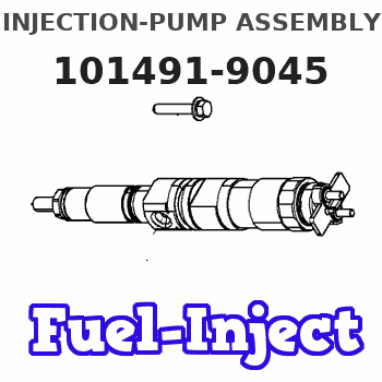
Information injection-pump assembly
ZEXEL
101491-9045
1014919045
Rating:
Cross reference number
ZEXEL
101491-9045
1014919045
Zexel num
Bosch num
Firm num
Name
101491-9045
INJECTION-PUMP ASSEMBLY
Calibration Data:
Adjustment conditions
Test oil
1404 Test oil ISO4113 or {SAEJ967d}
1404 Test oil ISO4113 or {SAEJ967d}
Test oil temperature
degC
40
40
45
Nozzle and nozzle holder
105780-8140
Bosch type code
EF8511/9A
Nozzle
105780-0000
Bosch type code
DN12SD12T
Nozzle holder
105780-2080
Bosch type code
EF8511/9
Opening pressure
MPa
17.2
Opening pressure
kgf/cm2
175
Injection pipe
Outer diameter - inner diameter - length (mm) mm 6-2-600
Outer diameter - inner diameter - length (mm) mm 6-2-600
Overflow valve opening pressure
kPa
157
123
191
Overflow valve opening pressure
kgf/cm2
1.6
1.25
1.95
Tester oil delivery pressure
kPa
157
157
157
Tester oil delivery pressure
kgf/cm2
1.6
1.6
1.6
Direction of rotation (viewed from drive side)
Right R
Right R
Injection timing adjustment
Direction of rotation (viewed from drive side)
Right R
Right R
Injection order
1-3-4-2
Pre-stroke
mm
3.4
3.35
3.45
Beginning of injection position
Drive side NO.1
Drive side NO.1
Difference between angles 1
Cal 1-3 deg. 90 89.5 90.5
Cal 1-3 deg. 90 89.5 90.5
Difference between angles 2
Cal 1-4 deg. 180 179.5 180.5
Cal 1-4 deg. 180 179.5 180.5
Difference between angles 3
Cyl.1-2 deg. 270 269.5 270.5
Cyl.1-2 deg. 270 269.5 270.5
Injection quantity adjustment
Adjusting point
-
Rack position
11.28+-0
.02
Pump speed
r/min
1000
1000
1000
Average injection quantity
mm3/st.
57.7
57.2
58.2
Max. variation between cylinders
%
0
-2.5
2.5
Basic
*
Fixing the rack
*
Standard for adjustment of the maximum variation between cylinders
*
Injection quantity adjustment_02
Adjusting point
H'
Rack position
9.6+-0.5
Pump speed
r/min
325
325
325
Average injection quantity
mm3/st.
9
7
11
Max. variation between cylinders
%
0
-14
14
Fixing the rack
*
Standard for adjustment of the maximum variation between cylinders
*
Injection quantity adjustment_03
Adjusting point
A
Rack position
11.28+-0
.5
Pump speed
r/min
1000
1000
1000
Average injection quantity
mm3/st.
57.7
57.2
58.2
Basic
*
Fixing the lever
*
Injection quantity adjustment_04
Adjusting point
B
Rack position
11.55+-0
.5
Pump speed
r/min
1700
1700
1700
Average injection quantity
mm3/st.
70
68
72
Fixing the lever
*
Injection quantity adjustment_05
Adjusting point
C
Rack position
11.39+-0
.5
Pump speed
r/min
625
625
625
Average injection quantity
mm3/st.
42.9
40.9
44.9
Fixing the lever
*
Injection quantity adjustment_06
Adjusting point
H
Rack position
9.3+-0.5
Pump speed
r/min
325
325
325
Average injection quantity
mm3/st.
7
6.5
7.5
Fixing the lever
*
Timer adjustment
Pump speed
r/min
1350+-25
Advance angle
deg.
0
0
0
Remarks
Start
Start
Timer adjustment_02
Pump speed
r/min
1700
Advance angle
deg.
3.5
3.2
3.8
Remarks
Finish
Finish
Test data Ex:
Governor adjustment
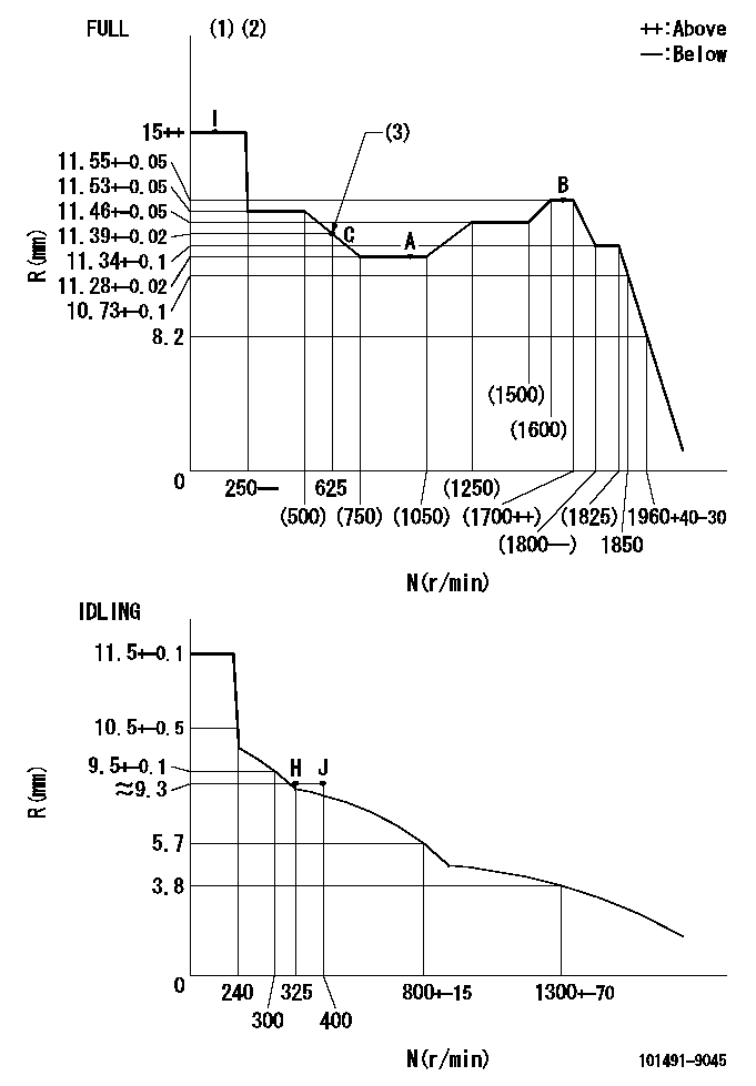
N:Pump speed
R:Rack position (mm)
(1)Torque cam stamping: T1
(2)Tolerance for racks not indicated: R1, speed N1
(3)Torque cam set point
----------
T1=C83 R1=+-0.02mm N1=+-3r/min
----------
----------
T1=C83 R1=+-0.02mm N1=+-3r/min
----------
Speed control lever angle

F:Full speed
I:Idle
(1)Stopper bolt set position 'H' (rack position = aa, speed = bb)
----------
aa=(9.3)mm bb=325r/min
----------
a=20deg+-5deg b=41deg+-3deg
----------
aa=(9.3)mm bb=325r/min
----------
a=20deg+-5deg b=41deg+-3deg
Stop lever angle

N:Pump normal
S:Stop the pump.
----------
----------
a=40deg+-5deg b=40deg+-5deg
----------
----------
a=40deg+-5deg b=40deg+-5deg
0000001501 GOV RACK POSITION CONFIRM
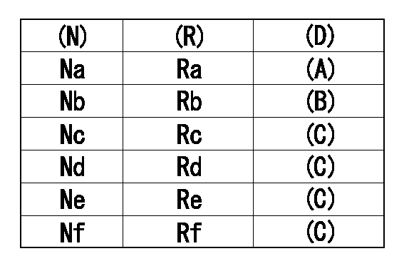
Confirm the governor adjustment rack position.
Standard point A
Set the torque cam B.
(C) Confirmation
(D) Remarks
(N): Speed of the pump
(R) Rack position (mm)
----------
----------
Na=1000r/min Nb=625r/min Nc=1800r/min Nd=1700r/min Ne=1400r/min Nf=450r/min Ra=11.28+-0.02mm Rb=11.39+-0.02mm Rc=11.34+-0.1mm Rd=11.55+-0.05mm Re=11.46+-0.05mm Rf=11.53+-0.05mm
----------
----------
Na=1000r/min Nb=625r/min Nc=1800r/min Nd=1700r/min Ne=1400r/min Nf=450r/min Ra=11.28+-0.02mm Rb=11.39+-0.02mm Rc=11.34+-0.1mm Rd=11.55+-0.05mm Re=11.46+-0.05mm Rf=11.53+-0.05mm
Timing setting

(1)Pump vertical direction
(2)Position of gear mark 'CC' at No 1 cylinder's beginning of injection
(3)-
(4)-
----------
----------
a=(130deg)
----------
----------
a=(130deg)
Information:
Caterpillar: Confidential Yellow
PSP FOR INSTALLING NEW FUEL INJECTION LINE BRACKETS AND CLAMPS ON CERTAIN D8L TRACTORS, D9N TRACTORS, 589 PIPELAYERS, 631E SCR APERS, 637E SCRAPERS, 657E SCRAPERS, 768C TRACTORS, 769C TRUCKS, 834B TRACTORS, AND 988B LOADERS - PS4428 - MAILED US AND CA NADA, CACO, COFA, BRAZIL, CFEL, COSA
The information supplied in this service letter may not be valid after the termination date of this program. Do not perform the work outlined in this Service Letter after the termination date without first contacting your Caterpillar product analyst.
U-63 A-35 AU-38 B-13 E-39 O-54 1252 PS4428 This Program can be administered either before or after a failure. In either case the decision whether to apply the Program is made by the dealer. When reporting the repair, use "PS4428" as Part Number, "7755" as Group Number, and "96" as Description Code. Termination Date
March 31, 1991
Problem
The fuel lines on certain D8L Tractors, D9N Tractors, 589 Pipelayers, 631E Scrapers, 637E Scrapers, 657E Scrapers, 768C Tractors, 769C Trucks, 834B Tractors, and 988B Loaders may fail. New brackets and clamps can be installed to increase the service life of the fuel injection lines.
Affected Product
Model Identification Number D8L 7YB962 7JC778 D9N 1JD1288, 1295, 1296, 1298-1356, 1358, 1361-2039, 2045, 2048, 2049, 2052 589 31Z423-452 631E 1AB965-1198, 1209 637E 1FB361-416, 418, 422 1JB612-724 657E
Have questions with 101491-9045?
Group cross 101491-9045 ZEXEL
Mazda
101491-9045
INJECTION-PUMP ASSEMBLY