Information injection-pump assembly
BOSCH
9 400 611 170
9400611170
ZEXEL
101491-1202
1014911202
MITSUBISHI
ME080004
me080004

Rating:
Service parts 101491-1202 INJECTION-PUMP ASSEMBLY:
1.
_
6.
COUPLING PLATE
7.
COUPLING PLATE
8.
_
9.
_
11.
Nozzle and Holder
ME019368
12.
Open Pre:MPa(Kqf/cm2)
17.7{180}
15.
NOZZLE SET
Cross reference number
BOSCH
9 400 611 170
9400611170
ZEXEL
101491-1202
1014911202
MITSUBISHI
ME080004
me080004
Zexel num
Bosch num
Firm num
Name
101491-1202
9 400 611 170
ME080004 MITSUBISHI
INJECTION-PUMP ASSEMBLY
4D31T K 14BC INJECTION PUMP ASSY PE4A,5A, PE
4D31T K 14BC INJECTION PUMP ASSY PE4A,5A, PE
Calibration Data:
Adjustment conditions
Test oil
1404 Test oil ISO4113 or {SAEJ967d}
1404 Test oil ISO4113 or {SAEJ967d}
Test oil temperature
degC
40
40
45
Nozzle and nozzle holder
105780-8140
Bosch type code
EF8511/9A
Nozzle
105780-0000
Bosch type code
DN12SD12T
Nozzle holder
105780-2080
Bosch type code
EF8511/9
Opening pressure
MPa
17.2
Opening pressure
kgf/cm2
175
Injection pipe
Outer diameter - inner diameter - length (mm) mm 6-2-600
Outer diameter - inner diameter - length (mm) mm 6-2-600
Overflow valve
131424-4620
Overflow valve opening pressure
kPa
255
221
289
Overflow valve opening pressure
kgf/cm2
2.6
2.25
2.95
Tester oil delivery pressure
kPa
157
157
157
Tester oil delivery pressure
kgf/cm2
1.6
1.6
1.6
Direction of rotation (viewed from drive side)
Right R
Right R
Injection timing adjustment
Direction of rotation (viewed from drive side)
Right R
Right R
Injection order
1-3-4-2
Pre-stroke
mm
3.2
3.15
3.25
Beginning of injection position
Drive side NO.1
Drive side NO.1
Difference between angles 1
Cal 1-3 deg. 90 89.5 90.5
Cal 1-3 deg. 90 89.5 90.5
Difference between angles 2
Cal 1-4 deg. 180 179.5 180.5
Cal 1-4 deg. 180 179.5 180.5
Difference between angles 3
Cyl.1-2 deg. 270 269.5 270.5
Cyl.1-2 deg. 270 269.5 270.5
Injection quantity adjustment
Adjusting point
A
Rack position
10.3
Pump speed
r/min
1000
1000
1000
Average injection quantity
mm3/st.
75.5
74.5
76.5
Max. variation between cylinders
%
0
-2.5
2.5
Basic
*
Fixing the lever
*
Injection quantity adjustment_02
Adjusting point
-
Rack position
7.8+-0.5
Pump speed
r/min
340
340
340
Average injection quantity
mm3/st.
8
7
9
Max. variation between cylinders
%
0
-14
14
Fixing the rack
*
Remarks
Adjust only variation between cylinders; adjust governor according to governor specifications.
Adjust only variation between cylinders; adjust governor according to governor specifications.
Injection quantity adjustment_03
Adjusting point
D
Rack position
-
Pump speed
r/min
100
100
100
Average injection quantity
mm3/st.
60.5
60.5
65.5
Fixing the lever
*
Rack limit
*
Timer adjustment
Pump speed
r/min
1050--
Advance angle
deg.
0
0
0
Remarks
Start
Start
Timer adjustment_02
Pump speed
r/min
1000
Advance angle
deg.
0.5
Timer adjustment_03
Pump speed
r/min
1100
Advance angle
deg.
0.5
0
1
Timer adjustment_04
Pump speed
r/min
-
Advance angle
deg.
3
3
3
Remarks
Measure the actual speed, stop
Measure the actual speed, stop
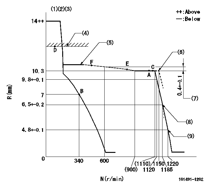
Test data Ex:
Governor adjustment

N:Pump speed
R:Rack position (mm)
(1)Target notch: K
(2)Tolerance for racks not indicated: +-0.05mm.
(3)Supplied with torque spring not set.
(4)RACK LIMIT
(5)The torque control spring must does not have a set force.
(6)Set at delivery
(7)Rack difference between N = N1 and N = N2
(8)Main spring setting
(9)Set idle sub-spring
----------
K=15 N1=1000r/min N2=600r/min
----------
----------
K=15 N1=1000r/min N2=600r/min
----------
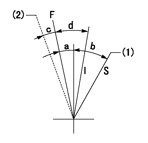
Speed control lever angle

F:Full speed
I:Idle
S:Stop
(1)Rack position = aa
(2)At delivery
----------
aa=1mm
----------
a=14deg+-5deg b=(35deg) c=(2deg) d=26deg+-5deg
----------
aa=1mm
----------
a=14deg+-5deg b=(35deg) c=(2deg) d=26deg+-5deg
Stop lever angle

N:Pump normal
S:Stop the pump.
----------
----------
a=27deg+-5deg b=53deg+-5deg
----------
----------
a=27deg+-5deg b=53deg+-5deg
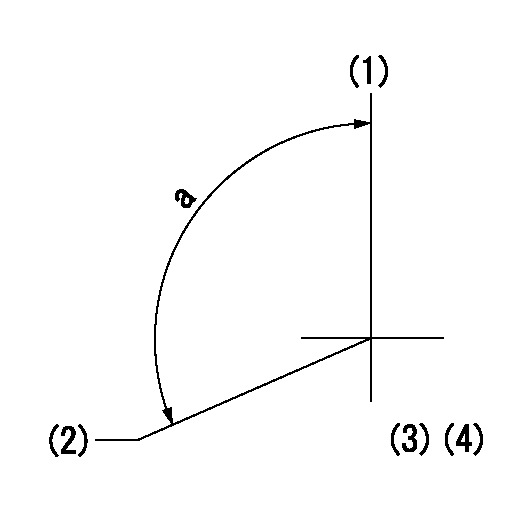
Timing setting

(1)Pump vertical direction
(2)Position of gear mark '3' at No 1 cylinder's beginning of injection
(3)B.T.D.C.: aa
(4)-
----------
aa=16deg
----------
a=(130deg)
----------
aa=16deg
----------
a=(130deg)
Information:
August 18, 2001
(Revised September 2001)
U-220
A-150
AU-137
H-72
O-163
TM-9
Priority PRODUCT IMPROVEMENT PROGRAMFOR TIGHTENING THE INJECTOR ROCKER ARM JAM NUTS ON CERTAIN 988G WHEEL LOADERS,834G WHEEL TRACTORS, AND 836G LANDFILL COMPACTORS
1123 PI30230
This Program must be administered assoon as possible. When reporting the repair, use "PI30230" as the Partnumber and "7751" as the Group Number, "56" as the Warranty Claim DescriptionCode and "T" as the SIMS Description Code. Exception: If the repair isdone after failure, use "PI30230" as the Part Number, "7751" as the GroupNumber, "96" as the Warranty Claim Description Code, and "Z" as the SIMSDescription Code. The information supplied in this serviceletter may not be valid after the termination date of this program. Donot perform the work outlined in this Service Letter after the terminationdate without first contacting your Caterpillar product analyst. This Revised Service Letter replacesthe August 18, 2001 Service Letter. Changes were made to the Affected Product.
COMPLETION DATE
TERMINATION DATE
February 28, 2002 August 31, 2002PROBLEM
The Injector rocker arm jam nuts on some 834GWheel Tractors, 836G Landfill Compactors, and 988G Wheel loaders are comingloose.AFFECTED PRODUCT
Model Identification Number
988G 2TW75-76, 78-79, 91-361,366-367
834G 6GZ168-203
836G 7MZ270-412, 414PARTS NEEDED
No Parts NeededACTION REQUIRED
Remove the valve covers.
Place a flat head screwdriver in the injectoradjusting screw and see if it will turn.
If the screw turns then the unit injector needsto be adjusted.(See step 5)
If the screw will NOT turn, mark a line acrossthe screw, nut, and injector arm with a colored marker. Use a dial typetorque wrench and tighten the adjusting jam nut to 100+-10 N m (74+=7FT-LBS). Check the line to see if the screw has turned in relation to theinjector arm. If the screw has moved more than 15 degrees in relation tothe arm, then the unit injector needs to be re-adjusted.
If a unit injector needs to be adjusted referto the Systems Operation Testing and Adjusting module for the procedureto adjust electronic unit injectors. Torque the jam nut to 100NM.
Enter the repair into SIMS.
OWNER NOTIFICATION
U.S. and Canadian owners will receive the attachedOwner Notification.SERVICE CLAIM ALLOWANCES
Caterpillar Dealer Suggested Customer Suggested
Parts Labor Hrs. Parts Labor Hrs. Parts Labor Hrs.
N/A 100% (*) 0 0 0 0
(*) 1.0 hour is allowed to Remove andInstall valve covers and torque the injector arm jam nuts. Six minutesis allowed to adjust each Unit Injector if needed - up to a maximum of.6 hours is allowed to adjust all six. U.S. and Canadian Dealers Only - Eligibledealers may enter a Type 2 SIMS ReportPARTS DISPOSITION
Handle the parts in accordance with your WarrantyBulletin on warranty parts handling.MAKE EVERY EFFORT TO COMPLETE THIS PROGRAMAS SOON AS POSSIBLE.
Attach. (1-Owner Notification)COPY OF OWNER NOTIFICATION FOR U.S. AND CANADIAN OWNERS
XYZ Corporation
3240 Arrow Drive
Anywhere, YZ 99999PRIORITY - TIGHTENING THE INJECTOR ROCKER ARMJAM NUTSMODELS INVOLVED ? Certain 988G Wheel Loaders,834G Wheel Tractors, and 836G Landfill CompactorsDear Caterpillar Product Owner:The injector rocker arm nuts need to be tightenedon the products listed below. The nuts need to be tightened to preventthem from coming loose. Loose jam nuts could possibly cause the injectorrocker arm(s) to break and the related cylinders would not fire. You willnot be charged for the service performed.Contact your local Caterpillar dealer immediatelyto schedule this service. The dealer will advise you of
Have questions with 101491-1202?
Group cross 101491-1202 ZEXEL
Mitsubishi
101491-1202
9 400 611 170
ME080004
INJECTION-PUMP ASSEMBLY
4D31T
4D31T
