Information injection-pump assembly
ZEXEL
101491-1100
1014911100
Rating:
Cross reference number
ZEXEL
101491-1100
1014911100
Zexel num
Bosch num
Firm num
Name
Calibration Data:
Adjustment conditions
Test oil
1404 Test oil ISO4113 or {SAEJ967d}
1404 Test oil ISO4113 or {SAEJ967d}
Test oil temperature
degC
40
40
45
Nozzle and nozzle holder
105780-8140
Bosch type code
EF8511/9A
Nozzle
105780-0000
Bosch type code
DN12SD12T
Nozzle holder
105780-2080
Bosch type code
EF8511/9
Opening pressure
MPa
17.2
Opening pressure
kgf/cm2
175
Injection pipe
Outer diameter - inner diameter - length (mm) mm 6-2-600
Outer diameter - inner diameter - length (mm) mm 6-2-600
Overflow valve
131424-4620
Overflow valve opening pressure
kPa
255
221
289
Overflow valve opening pressure
kgf/cm2
2.6
2.25
2.95
Tester oil delivery pressure
kPa
157
157
157
Tester oil delivery pressure
kgf/cm2
1.6
1.6
1.6
Direction of rotation (viewed from drive side)
Right R
Right R
Injection timing adjustment
Direction of rotation (viewed from drive side)
Right R
Right R
Injection order
1-3-4-2
Pre-stroke
mm
3.2
3.15
3.25
Beginning of injection position
Drive side NO.1
Drive side NO.1
Difference between angles 1
Cal 1-3 deg. 90 89.5 90.5
Cal 1-3 deg. 90 89.5 90.5
Difference between angles 2
Cal 1-4 deg. 180 179.5 180.5
Cal 1-4 deg. 180 179.5 180.5
Difference between angles 3
Cyl.1-2 deg. 270 269.5 270.5
Cyl.1-2 deg. 270 269.5 270.5
Injection quantity adjustment
Adjusting point
A
Rack position
9.7
Pump speed
r/min
1000
1000
1000
Average injection quantity
mm3/st.
64.5
63.5
65.5
Max. variation between cylinders
%
0
-2.5
2.5
Basic
*
Fixing the lever
*
Injection quantity adjustment_02
Adjusting point
B
Rack position
8.2+-0.5
Pump speed
r/min
375
375
375
Average injection quantity
mm3/st.
7.5
6.2
8.8
Max. variation between cylinders
%
0
-14
14
Fixing the rack
*
Remarks
Adjust only variation between cylinders; adjust governor according to governor specifications.
Adjust only variation between cylinders; adjust governor according to governor specifications.
Injection quantity adjustment_03
Adjusting point
C
Rack position
11.6+-0.
5
Pump speed
r/min
100
100
100
Average injection quantity
mm3/st.
60.5
60.5
65.5
Fixing the lever
*
Rack limit
*
Timer adjustment
Pump speed
r/min
1270--
Advance angle
deg.
0
0
0
Remarks
Start
Start
Timer adjustment_02
Pump speed
r/min
1200
Advance angle
deg.
0.5
Timer adjustment_03
Pump speed
r/min
1500
Advance angle
deg.
1.5
1.2
1.8
Timer adjustment_04
Pump speed
r/min
-
Advance angle
deg.
3
3
3
Remarks
Measure the actual speed, stop
Measure the actual speed, stop
Test data Ex:
Governor adjustment
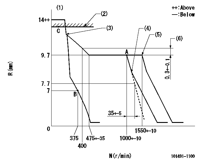
N:Pump speed
R:Rack position (mm)
(1)Target notch: K
(2)RACK LIMIT
(3)The torque control spring must does not have a set force.
(4)Idle sub spring setting: L1.
(5)Torque spring does not operate.
(6)Rack difference between N = N1 and N = N2
----------
K=6 L1=8.9+-0.1mm N1=1000r/min N2=400r/min
----------
----------
K=6 L1=8.9+-0.1mm N1=1000r/min N2=400r/min
----------
Speed control lever angle
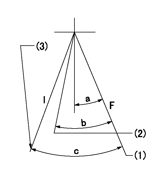
F:Full speed
I:Idle
(1)Set the pump speed at aa
(2)Pump speed = bb
(3)Stopper bolt setting
----------
aa=1550r/min bb=1000r/min
----------
a=10deg+-5deg b=15deg+-5deg c=30deg+-5deg
----------
aa=1550r/min bb=1000r/min
----------
a=10deg+-5deg b=15deg+-5deg c=30deg+-5deg
Stop lever angle

N:Pump normal
S:Stop the pump.
----------
----------
a=27deg+-5deg b=53deg+-5deg
----------
----------
a=27deg+-5deg b=53deg+-5deg
Timing setting

(1)Pump vertical direction
(2)Position of gear mark '3' at No 1 cylinder's beginning of injection
(3)B.T.D.C.: aa
(4)-
----------
aa=16deg
----------
a=(130deg)
----------
aa=16deg
----------
a=(130deg)
Information:
Start By:a. remove oil pumpb. remove oil pan plate 1. Remove No. 1, 3, 5 and 7 main bearing caps (1). Remove the lower halves of the main bearings from the main bearing caps.
If the crankshaft is turned in the wrong direction, the tab on the bearing will be pushed between the crankshaft and the bearing area in the cylinder block. This can result in damage to the cylinder block and/or the crankshaft.
2. Install Tool (A) in the hole in the crankshaft journal, and turn the crankshaft to remove the upper halves of main bearings (2).3. Remove crankshaft thrust bearings (3) from the rear main bearing. Install the main bearings dry when the clearance checks are made. Put clean engine oil on the main bearings for final assembly.
Make sure the upper and lower halves of the main bearings are installed so the bearing tabs fit into the notch in the cylinder block and the main bearing caps.
4. Use Tool (A), and install new upper halves of main bearings (2) in the cylinder block. Install new lower halves of main bearings (2) in main bearing caps (1).
When the bearing clearance is checked and the engine is in an upright position (vertical position with cylinder head on top), the crankshaft will have to be lifted up and held against the upper halves of the main bearings to get a correct measurement with the Plastigage. The Plastigage will not hold the weight of the crankshaft and give a correct indication. If the engine is in a horizontal position, it is not necessary to hold the crankshaft up. Do not turn the crankshaft when the Plastigage is in position to check clearances.
For complete details concerning measuring bearing clearances, see Engine Bearings And Crankshafts, Form No. SEBD0531.5. Check the main bearing clearance with Plastigage (B) as follows:a. Put a piece of Plastigage (B) on the crankshaft journals as shown.
Make sure the part number on the main bearing cap is toward the front of the engine and the number on the main bearing cap is the same as the number on the cylinder block on the left side of each main bearing cap.
b. Put main bearing caps (1) in position in the engine. Put 2P2506 Thread Lubricant on the bolt threads and the face of the washers. Install the bolts. Tighten the bolts to a torque of 40 4 N m (30 3 lb ft).c. Put a mark on each bolt and main bearing cap; then tighten the bolts 90° more.d. Remove the main bearing caps, and measure the Plastigage to find the bearing clearance. The main bearing clearance for new bearings must be 0.076 to 0.165 mm (.0030 to .0065 in.). Maximum permissible clearance with used bearings is 0.25 mm (.010 in.). 6. Put clean oil on the thrust bearing, and install a new thrust bearing for the rear main bearing. Install the thrust bearing with the identification "BLOCK SIDE" toward the cylinder block and the tabs on the thrust bearings