Information injection-pump assembly
ZEXEL
101491-1070
1014911070

Rating:
Service parts 101491-1070 INJECTION-PUMP ASSEMBLY:
1.
_
3.
GOVERNOR
6.
COUPLING PLATE
7.
COUPLING PLATE
8.
_
9.
_
11.
Nozzle and Holder
ME790067
12.
Open Pre:MPa(Kqf/cm2)
21.6{220}

15.
NOZZLE SET
Cross reference number
ZEXEL
101491-1070
1014911070
Zexel num
Bosch num
Firm num
Name
Calibration Data:
Adjustment conditions
Test oil
1404 Test oil ISO4113 or {SAEJ967d}
1404 Test oil ISO4113 or {SAEJ967d}
Test oil temperature
degC
40
40
45
Nozzle and nozzle holder
105780-8140
Bosch type code
EF8511/9A
Nozzle
105780-0000
Bosch type code
DN12SD12T
Nozzle holder
105780-2080
Bosch type code
EF8511/9
Opening pressure
MPa
17.2
Opening pressure
kgf/cm2
175
Injection pipe
Outer diameter - inner diameter - length (mm) mm 6-2-600
Outer diameter - inner diameter - length (mm) mm 6-2-600
Overflow valve
131424-5620
Overflow valve opening pressure
kPa
157
123
191
Overflow valve opening pressure
kgf/cm2
1.6
1.25
1.95
Tester oil delivery pressure
kPa
157
157
157
Tester oil delivery pressure
kgf/cm2
1.6
1.6
1.6
Direction of rotation (viewed from drive side)
Right R
Right R
Injection timing adjustment
Direction of rotation (viewed from drive side)
Right R
Right R
Injection order
1-3-4-2
Pre-stroke
mm
3.5
3.45
3.55
Beginning of injection position
Drive side NO.1
Drive side NO.1
Difference between angles 1
Cal 1-3 deg. 90 89.5 90.5
Cal 1-3 deg. 90 89.5 90.5
Difference between angles 2
Cal 1-4 deg. 180 179.5 180.5
Cal 1-4 deg. 180 179.5 180.5
Difference between angles 3
Cyl.1-2 deg. 270 269.5 270.5
Cyl.1-2 deg. 270 269.5 270.5
Injection quantity adjustment
Adjusting point
-
Rack position
11.45
Pump speed
r/min
1000
1000
1000
Average injection quantity
mm3/st.
66.5
65.5
67.5
Max. variation between cylinders
%
0
-2.5
2.5
Basic
*
Fixing the rack
*
Standard for adjustment of the maximum variation between cylinders
*
Injection quantity adjustment_02
Adjusting point
H
Rack position
9.7+-0.5
Pump speed
r/min
325
325
325
Average injection quantity
mm3/st.
10
8.7
11.3
Max. variation between cylinders
%
0
-10
10
Fixing the rack
*
Standard for adjustment of the maximum variation between cylinders
*
Remarks
Adjust only variation between cylinders; adjust governor according to governor specifications.
Adjust only variation between cylinders; adjust governor according to governor specifications.
Injection quantity adjustment_03
Adjusting point
A
Rack position
R1(11.45
)
Pump speed
r/min
1000
1000
1000
Average injection quantity
mm3/st.
66.5
65.5
67.5
Basic
*
Fixing the lever
*
Boost pressure
kPa
44
44
Boost pressure
mmHg
330
330
Injection quantity adjustment_04
Adjusting point
B
Rack position
R1+0.2
Pump speed
r/min
1750
1750
1750
Average injection quantity
mm3/st.
75.5
73.5
77.5
Fixing the lever
*
Boost pressure
kPa
44
44
Boost pressure
mmHg
330
330
Injection quantity adjustment_05
Adjusting point
C
Rack position
R1-0.35
Pump speed
r/min
700
700
700
Average injection quantity
mm3/st.
47.5
45.5
49.5
Fixing the lever
*
Boost pressure
kPa
0
0
0
Boost pressure
mmHg
0
0
0
Injection quantity adjustment_06
Adjusting point
I
Rack position
14.8+-0.
5
Pump speed
r/min
100
100
100
Average injection quantity
mm3/st.
66
66
71
Fixing the lever
*
Rack limit
*
Boost compensator adjustment
Pump speed
r/min
700
700
700
Rack position
R1-0.35
Boost pressure
kPa
20
18.7
21.3
Boost pressure
mmHg
150
140
160
Boost compensator adjustment_02
Pump speed
r/min
700
700
700
Rack position
R1(11.45
)
Boost pressure
kPa
30.7
24
37.4
Boost pressure
mmHg
230
180
280
Timer adjustment
Pump speed
r/min
1400+70
Advance angle
deg.
0
0
0
Remarks
Start
Start
Timer adjustment_02
Pump speed
r/min
1750
Advance angle
deg.
5
4.5
5.5
Remarks
Finish
Finish
Test data Ex:
Governor adjustment
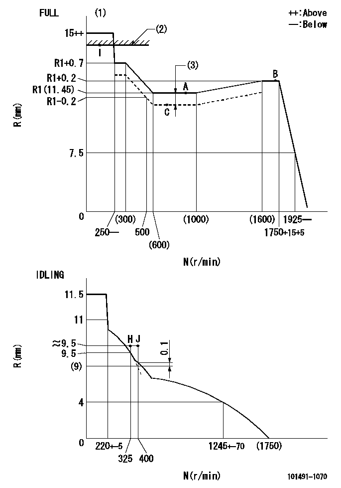
N:Pump speed
R:Rack position (mm)
(1)Torque cam stamping: T1
(2)RACK LIMIT: RAL
(3)Boost compensator stroke: BCL
----------
T1=76 RAL=(14.8)mm BCL=0.35+-0.1mm
----------
----------
T1=76 RAL=(14.8)mm BCL=0.35+-0.1mm
----------
Speed control lever angle

F:Full speed
I:Idle
(1)Stopper bolt set position 'H'
----------
----------
a=26deg+-5deg b=42deg+-3deg
----------
----------
a=26deg+-5deg b=42deg+-3deg
Stop lever angle
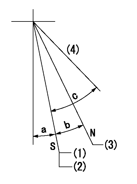
N:Pump normal
S:Stop the pump.
(1)Set the stopper bolt at speed = aa and rack position = bb.
(2)After setting the stopper bolt, confirm non-injection at speed = cc. Rack position = dd or less.
(3)Rack position = approximately ee.
(4)Free (at shipping)
----------
aa=1700r/min bb=6.5-0.5mm cc=325r/min dd=8mm ee=16mm
----------
a=8deg+-5deg b=15deg+-3deg c=25deg+-5deg
----------
aa=1700r/min bb=6.5-0.5mm cc=325r/min dd=8mm ee=16mm
----------
a=8deg+-5deg b=15deg+-3deg c=25deg+-5deg
0000001501 MICRO SWITCH
Adjustment of the micro-switch
Adjust the bolt to obtain the following lever position when the micro-switch is ON.
(1)Speed N1
(2)Rack position Ra
----------
N1=350r/min Ra=9.5mm
----------
----------
N1=350r/min Ra=9.5mm
----------
Timing setting

(1)Pump vertical direction
(2)Position of gear mark '3' at No 1 cylinder's beginning of injection
(3)B.T.D.C.: aa
(4)-
----------
aa=10deg
----------
a=(130deg)
----------
aa=10deg
----------
a=(130deg)
Information:
1. Remove bolts (1) and the washers that hold rocker shaft assembly (2) in position.2. Remove rocker shaft assembly (2). Remove the O-ring seal from the rear rocker arm support bracket.3. Put identification marks on push rods (3) as to their location in the engine. Remove the push rods.Install Rocker Shaft Assembly & Push Rods
1. Install push rods (1). Make sure they are in their original location in the engine and in position in the valve lifters.
Loosen the adjusting screws on the rocker arms. This will prevent a bent valve or push rod during installation of the rocker shaft assembly.
2. Install a new O-ring seal in the rear rocker arm support bracket. Put 2P2506 Thread Lubricant on all of the bolts that hold the rocker shaft assembly in position except for the bolt that goes through the rear rocker arm support bracket.3. Put rocker shaft assembly (2) in position on the engine. Make sure the dowels in the support bracket are in alignment with the dowel holes in the cylinder head. Make sure the rocker arms are engaged with the push rods.4. Install the bolts and washers that hold the rocker shaft assembly in position. Tighten them until they are finger tight.
3304 Engine Sequence
3306 Engine Sequence5. Tighten the bolts that hold the rocker shaft as follows:a. Tighten the bolts in number sequence to a torque of 156 N m (115 lb ft).b. Tighten the bolts in number sequence to a torque of 250 17 N m (185 13 lb ft).c. Tighten the bolts again in number sequence to a torque of 250 17 N m (185 13 lb ft).6. See "Valve Clearance Setting" in Testing & Adjusting. Make an adjustment to the valves so the intake valves have 0.38 mm (.015 in) clearance and the exhaust valves have 0.64 mm (.025 in) clearance. Tighten the locknuts for the adjusting screws to a torque of 29 7 N m (21 5 lb ft).End By:a. install valve cover