Information injection-pump assembly
ZEXEL
101491-1060
1014911060

Rating:
Cross reference number
ZEXEL
101491-1060
1014911060
Zexel num
Bosch num
Firm num
Name
Calibration Data:
Adjustment conditions
Test oil
1404 Test oil ISO4113 or {SAEJ967d}
1404 Test oil ISO4113 or {SAEJ967d}
Test oil temperature
degC
40
40
45
Nozzle and nozzle holder
105780-8140
Bosch type code
EF8511/9A
Nozzle
105780-0000
Bosch type code
DN12SD12T
Nozzle holder
105780-2080
Bosch type code
EF8511/9
Opening pressure
MPa
17.2
Opening pressure
kgf/cm2
175
Injection pipe
Outer diameter - inner diameter - length (mm) mm 6-2-600
Outer diameter - inner diameter - length (mm) mm 6-2-600
Overflow valve
131424-5620
Overflow valve opening pressure
kPa
157
123
191
Overflow valve opening pressure
kgf/cm2
1.6
1.25
1.95
Tester oil delivery pressure
kPa
157
157
157
Tester oil delivery pressure
kgf/cm2
1.6
1.6
1.6
Direction of rotation (viewed from drive side)
Right R
Right R
Injection timing adjustment
Direction of rotation (viewed from drive side)
Right R
Right R
Injection order
1-3-4-2
Pre-stroke
mm
3.5
3.45
3.55
Beginning of injection position
Drive side NO.1
Drive side NO.1
Difference between angles 1
Cal 1-3 deg. 90 89.5 90.5
Cal 1-3 deg. 90 89.5 90.5
Difference between angles 2
Cal 1-4 deg. 180 179.5 180.5
Cal 1-4 deg. 180 179.5 180.5
Difference between angles 3
Cyl.1-2 deg. 270 269.5 270.5
Cyl.1-2 deg. 270 269.5 270.5
Injection quantity adjustment
Adjusting point
-
Rack position
10.7
Pump speed
r/min
1000
1000
1000
Average injection quantity
mm3/st.
56
55
57
Max. variation between cylinders
%
0
-2.5
2.5
Basic
*
Fixing the rack
*
Standard for adjustment of the maximum variation between cylinders
*
Injection quantity adjustment_02
Adjusting point
H
Rack position
9.7+-0.5
Pump speed
r/min
325
325
325
Average injection quantity
mm3/st.
10
8.7
11.3
Max. variation between cylinders
%
0
-10
10
Fixing the rack
*
Standard for adjustment of the maximum variation between cylinders
*
Remarks
Adjust only variation between cylinders; adjust governor according to governor specifications.
Adjust only variation between cylinders; adjust governor according to governor specifications.
Injection quantity adjustment_03
Adjusting point
A
Rack position
R1(10.7)
Pump speed
r/min
1000
1000
1000
Average injection quantity
mm3/st.
56
55
57
Basic
*
Fixing the lever
*
Boost pressure
kPa
42.7
42.7
Boost pressure
mmHg
320
320
Injection quantity adjustment_04
Adjusting point
B
Rack position
R1+0.2
Pump speed
r/min
1750
1750
1750
Average injection quantity
mm3/st.
63.5
59.5
67.5
Fixing the lever
*
Boost pressure
kPa
42.7
42.7
Boost pressure
mmHg
320
320
Injection quantity adjustment_05
Adjusting point
C
Rack position
R1-0.8
Pump speed
r/min
700
700
700
Average injection quantity
mm3/st.
38
34
42
Fixing the lever
*
Boost pressure
kPa
0
0
0
Boost pressure
mmHg
0
0
0
Injection quantity adjustment_06
Adjusting point
D
Rack position
R1-0.1
Pump speed
r/min
500
500
500
Average injection quantity
mm3/st.
34
30
38
Fixing the lever
*
Boost pressure
kPa
0
0
0
Boost pressure
mmHg
0
0
0
Injection quantity adjustment_07
Adjusting point
I
Rack position
14.8+-0.
5
Pump speed
r/min
100
100
100
Average injection quantity
mm3/st.
66
66
71
Fixing the lever
*
Rack limit
*
Boost compensator adjustment
Pump speed
r/min
700
700
700
Rack position
R1-0.8
Boost pressure
kPa
5.3
4
6.6
Boost pressure
mmHg
40
30
50
Boost compensator adjustment_02
Pump speed
r/min
700
700
700
Rack position
R1(10.7)
Boost pressure
kPa
28.7
22
35.4
Boost pressure
mmHg
215
165
265
Timer adjustment
Pump speed
r/min
1400
Advance angle
deg.
0
0
0
Remarks
Start
Start
Timer adjustment_02
Pump speed
r/min
1750
Advance angle
deg.
5
4.5
5.5
Remarks
Finish
Finish
Test data Ex:
Governor adjustment
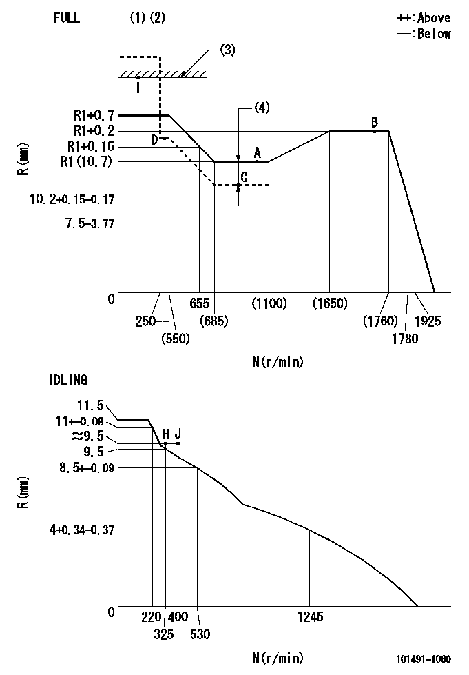
N:Pump speed
R:Rack position (mm)
(1)Torque cam stamping: T1
(2)Tolerance for racks not indicated: +-0.05mm.
(3)RACK LIMIT
(4)Boost compensator stroke: BCL
----------
T1=K15 BCL=0.8+-0.1mm
----------
----------
T1=K15 BCL=0.8+-0.1mm
----------
Speed control lever angle

F:Full speed
I:Idle
(1)Stopper bolt set position 'H'
----------
----------
a=26deg+-5deg b=42deg+-3deg
----------
----------
a=26deg+-5deg b=42deg+-3deg
Stop lever angle
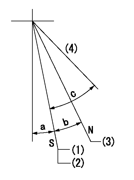
N:Pump normal
S:Stop the pump.
(1)Set the stopper bolt at speed = aa and rack position = bb.
(2)After setting the stopper bolt, confirm non-injection at speed = cc. Rack position = dd or less.
(3)Rack position = approximately ee.
(4)Free (at shipping)
----------
aa=1700r/min bb=6.5-0.5mm cc=325r/min dd=8mm ee=16mm
----------
a=8deg+-5deg b=15deg+-3deg c=(25deg)
----------
aa=1700r/min bb=6.5-0.5mm cc=325r/min dd=8mm ee=16mm
----------
a=8deg+-5deg b=15deg+-3deg c=(25deg)
0000001501 MICRO SWITCH
Adjustment of the micro-switch
Adjust the bolt to obtain the following lever position when the micro-switch is ON.
(1)Speed N1
(2)Rack position Ra
----------
N1=350r/min Ra=9.5+-0.1mm
----------
----------
N1=350r/min Ra=9.5+-0.1mm
----------
Timing setting

(1)Pump vertical direction
(2)Position of gear mark '3' at No 1 cylinder's beginning of injection
(3)B.T.D.C.: aa
(4)-
----------
aa=10deg
----------
a=(130deg)
----------
aa=10deg
----------
a=(130deg)
Information:
Start By:a. remove turbocharger 1. Install the turbocharger on Tool (A).2. Put alignment marks on the two housings and cartridge assembly of the turbocharger for correct alignment during assembly.3. Loosen clamp (3), and remove compressor housing (4) from cartridge assembly (2).4. Loosen the remaining clamp, and remove cartridge assembly (2) from turbine housing (1).
Typical Example5. Put the cartridge group (shown in the illustration) with nut (16) up in Tool (B). Use a 5S9566 Sliding T-Wrench and a universal socket to remove nut (16) that holds the compressor wheel (15) to the wheel assembly (19).6. Remove compressor wheel (15) and housing assembly (6) from wheel assembly (19). Remove piston ring (13) from the wheel assembly.7. Use Tool (C), and remove snap ring (5) from housing assembly (6). Remove insert (14) and sleeve (18) from the housing assembly. Remove seal (22) from insert (14). Remove ring (20) from sleeve (18).8. Remove oil deflector (23), thrust ring (21), bearing assembly (7), spacer sleeve (24) and thrust ring (8) from housing assembly (6).9. Use Tool (D), and remove snap ring (9) from the housing assembly. Remove bearing (25). Remove snap ring (10) with Tool (D).10. Use Tool (D), and remove snap ring (12) from the housing assembly. Remove bearing (26). Remove snap ring (11) with Tool (D).11. Check all the parts of the turbocharger for damage. If any parts are damaged, use new parts for replacement. See Special Instruction Form No. SMHS6854 for turbocharger reconditioning. Also, see Guidelines For Reusable Parts, Form No. SEBF8018. The following steps are for assembly of the turbocharger.12. Make sure that all the oil passages in the turbocharger cartridge housing are clean and free of dirt and foreign material. Do not put oil on any parts of the turbocharger until after the compressor wheel has been installed. After the turbocharger has been assembled, put clean engine oil into the oil inlet of the turbocharger.
Make sure the snap rings that hold bearings (25) and (26) in housing assembly (6) are installed with the round edge of the outside diameter toward the bearing.
13. Install snap ring (11) with Tool (D). Install bearing (26). Install snap ring (12) with Tool (D).14. Install snap ring (10) with Tool (D). Install bearing (25). Install snap ring (9) with Tool (D).15. Put wheel assembly (19) in position on Tool (B) with the threaded portion end up. Put 6V2055 High Vacuum Grease in the groove for piston ring (13) at assembly to one half or more of the depth of the groove all the way around.16. Install piston ring (13) in the groove in wheel assembly (19).17. Put housing assembly (6) in position on wheel assembly (19).18. Install thrust ring (8) and spacer sleeve (24) on wheel assembly (19).19. Make sure the screen is in place in bearing assembly (7). Install bearing assembly (7) over spacer sleeve (24). Make sure the screen in the bearing assembly is facing toward housing assembly (6) when it is installed.20. Install thrust ring (21) and oil deflector (23)