Information injection-pump assembly
ZEXEL
101491-1031
1014911031
Rating:
Service parts 101491-1031 INJECTION-PUMP ASSEMBLY:
1.
_
3.
GOVERNOR
6.
COUPLING PLATE
7.
COUPLING PLATE
8.
_
9.
_
11.
Nozzle and Holder
ME790067
12.
Open Pre:MPa(Kqf/cm2)
21.6{220}

15.
NOZZLE SET
Cross reference number
ZEXEL
101491-1031
1014911031
Zexel num
Bosch num
Firm num
Name
Calibration Data:
Adjustment conditions
Test oil
1404 Test oil ISO4113 or {SAEJ967d}
1404 Test oil ISO4113 or {SAEJ967d}
Test oil temperature
degC
40
40
45
Nozzle and nozzle holder
105780-8140
Bosch type code
EF8511/9A
Nozzle
105780-0000
Bosch type code
DN12SD12T
Nozzle holder
105780-2080
Bosch type code
EF8511/9
Opening pressure
MPa
17.2
Opening pressure
kgf/cm2
175
Injection pipe
Outer diameter - inner diameter - length (mm) mm 6-2-600
Outer diameter - inner diameter - length (mm) mm 6-2-600
Overflow valve
131424-5620
Overflow valve opening pressure
kPa
157
123
191
Overflow valve opening pressure
kgf/cm2
1.6
1.25
1.95
Tester oil delivery pressure
kPa
157
157
157
Tester oil delivery pressure
kgf/cm2
1.6
1.6
1.6
Direction of rotation (viewed from drive side)
Right R
Right R
Injection timing adjustment
Direction of rotation (viewed from drive side)
Right R
Right R
Injection order
1-3-4-2
Pre-stroke
mm
3.5
3.45
3.55
Beginning of injection position
Drive side NO.1
Drive side NO.1
Difference between angles 1
Cal 1-3 deg. 90 89.5 90.5
Cal 1-3 deg. 90 89.5 90.5
Difference between angles 2
Cal 1-4 deg. 180 179.5 180.5
Cal 1-4 deg. 180 179.5 180.5
Difference between angles 3
Cyl.1-2 deg. 270 269.5 270.5
Cyl.1-2 deg. 270 269.5 270.5
Injection quantity adjustment
Adjusting point
-
Rack position
11.45
Pump speed
r/min
1000
1000
1000
Average injection quantity
mm3/st.
66.5
65.5
67.5
Max. variation between cylinders
%
0
-2.5
2.5
Basic
*
Fixing the rack
*
Standard for adjustment of the maximum variation between cylinders
*
Injection quantity adjustment_02
Adjusting point
H
Rack position
9.7+-0.5
Pump speed
r/min
325
325
325
Average injection quantity
mm3/st.
10
8.7
11.3
Max. variation between cylinders
%
0
-10
10
Fixing the rack
*
Standard for adjustment of the maximum variation between cylinders
*
Remarks
Adjust only variation between cylinders; adjust governor according to governor specifications.
Adjust only variation between cylinders; adjust governor according to governor specifications.
Injection quantity adjustment_03
Adjusting point
A
Rack position
R1(11.45
)
Pump speed
r/min
1000
1000
1000
Average injection quantity
mm3/st.
66.5
65.5
67.5
Fixing the lever
*
Boost pressure
kPa
44
44
Boost pressure
mmHg
330
330
Injection quantity adjustment_04
Adjusting point
B
Rack position
R1+0.2
Pump speed
r/min
1750
1750
1750
Average injection quantity
mm3/st.
75.5
73.5
77.5
Fixing the lever
*
Boost pressure
kPa
44
44
Boost pressure
mmHg
330
330
Injection quantity adjustment_05
Adjusting point
C
Rack position
R1-0.35
Pump speed
r/min
700
700
700
Average injection quantity
mm3/st.
47.5
45.5
49.5
Fixing the lever
*
Boost pressure
kPa
0
0
0
Boost pressure
mmHg
0
0
0
Injection quantity adjustment_06
Adjusting point
I
Rack position
14.8+-0.
5
Pump speed
r/min
100
100
100
Average injection quantity
mm3/st.
66
66
71
Fixing the lever
*
Rack limit
*
Boost compensator adjustment
Pump speed
r/min
700
700
700
Rack position
R1-0.35
Boost pressure
kPa
20
18.7
21.3
Boost pressure
mmHg
150
140
160
Boost compensator adjustment_02
Pump speed
r/min
700
700
700
Rack position
R1(11.45
)
Boost pressure
kPa
30.7
24
37.4
Boost pressure
mmHg
230
180
280
Timer adjustment
Pump speed
r/min
1400
Advance angle
deg.
0
0
0
Remarks
Start
Start
Timer adjustment_02
Pump speed
r/min
1650
Advance angle
deg.
3
2.5
3.5
Remarks
Finish
Finish
Test data Ex:
Governor adjustment
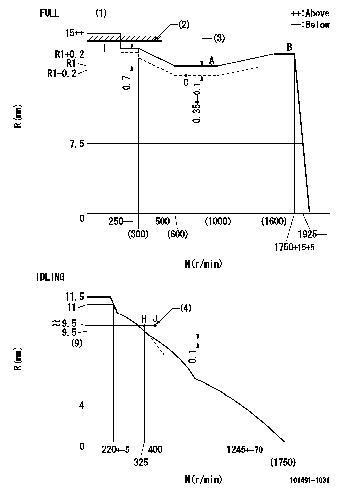
N:Pump speed
R:Rack position (mm)
(1)Torque cam stamping: T1
(2)RACK LIMIT: RAL
(3)Boost compensator stroke
(4)Lever set point at operating limit of increased fuel quantity for starting
----------
T1=76 RAL=(14.8)mm
----------
----------
T1=76 RAL=(14.8)mm
----------
Speed control lever angle

F:Full speed
I:Idle
(1)Stopper bolt set position 'H'
----------
----------
a=26deg+-5deg b=42deg+-3deg
----------
----------
a=26deg+-5deg b=42deg+-3deg
Stop lever angle
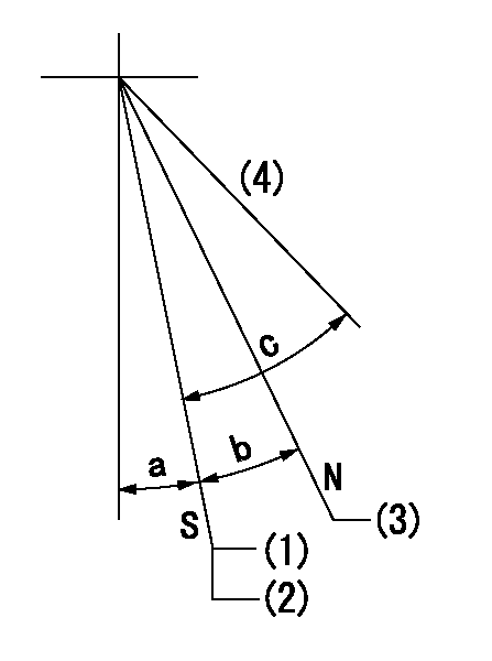
N:Pump normal
S:Stop the pump.
(1)Set the stopper bolt at speed = aa and rack position = bb.
(2)After setting the stopper bolt, confirm non-injection at speed = cc. Rack position = dd or less.
(3)Rack position = approximately ee.
(4)Free (at shipping)
----------
aa=1700r/min bb=6.5-0.5mm cc=325r/min dd=8mm ee=16mm
----------
a=8deg+-5deg b=15deg+-3deg c=25deg+-5deg
----------
aa=1700r/min bb=6.5-0.5mm cc=325r/min dd=8mm ee=16mm
----------
a=8deg+-5deg b=15deg+-3deg c=25deg+-5deg
0000001501 MICRO SWITCH
Adjustment of the micro-switch
Adjust the bolt to obtain the following lever position when the micro-switch is ON.
(1)Speed N1
(2)Rack position Ra
----------
N1=350r/min Ra=9.5mm
----------
----------
N1=350r/min Ra=9.5mm
----------
Timing setting

(1)Pump vertical direction
(2)Position of gear mark '3' at No 1 cylinder's beginning of injection
(3)B.T.D.C.: aa
(4)-
----------
aa=10deg
----------
a=(130deg)
----------
aa=10deg
----------
a=(130deg)
Information:
Start By:a. remove fuel injection lines 1. Remove bolt (1) and clamp (2) from the fuel injection nozzles to be removed.2. Install Tool (A) with the inside lip of the puller on the lower stepped diameter of the nozzle and the tip of the button in the threaded hole for bolt (1).
Do not exceed a torque of 17 N m (150 lb in) on the screw of Tool (A) during removal of the nozzle. Added force can cause the stem of the nozzle to bend or break off.
3. Tighten the screw of Tool (A) to a maximum torque of 17 N m (150 lb in) to remove fuel injection nozzle (3).4. If the fuel injection nozzle can not be removed with a maximum torque of 17 N m (150 lb in) on the screw of Tool (A), remove Tool (A).
Typical Example5. Remove the protective cap from fuel injection nozzle (3), and install Tool (B) as shown.
Hold Tool (B) so the center line of the tool is in alignment with the centerline of fuel injection nozzle (3). This will prevent distortion of the nozzle which can cause it to bend or break off during removal.
6. Remove the fuel injection nozzle with Tool (B).7. If Tool (B) was used to remove the fuel injection nozzle, replace the nozzle.8. If Tool (A) was used to remove the fuel injection nozzle, remove the carbon dam seal on the end of the nozzle.Install Fuel Injection Nozzle
1. Use Tool (C) to clean the bore for the fuel injection nozzle. Use an open end wrench or tap driver to turn Tool (C).2. Make reference to Special Instruction, Form No. SEHS7292, for the use of Tool (D). Clean the fuel injection nozzle with Tool (D). 3. Install a new seal (4) on fuel injection nozzle (3).4. Put carbon dam seal (5) on the small end of Tool (E). Expand the carbon dam seal by sliding it to the large end. Put Tool (E) against the fuel injection nozzle. Slide carbon dam seal (5) off Tool (E) on to the nozzle. Slide the carbon dam seal into position in the groove on the nozzle as shown. 5. Put fuel injection nozzle (3) in position in the cylinder head. Install clamp (2) and bolt (1) to hold the nozzle in position.End By:a. install fuel injection lines